email: tony@lathes.co.uk
Home   Machine Tool Archive   Machine-tools for Sale & Wanted
Machine Tool Manuals   Machine Tool Catalogues   Belts   
Books   Accessories


Emco Unimat DB200 & SL1000 Accessories
Unimat Home Page  Emco Home Page  Accessories  Earliest Unimat - Photographs Page 1 and Page 2
     
Mk. 2 & 2A  Photographs  Mk. 2B Photographs  SL1000/DB200 Photographs 

Russian Copy  Unimat Nameplates  Unknown  Motors  Motor Repair  Computer Control

Home-made Unimat No.1   Home-made Unimat No.2   ROWIC - Argentinean Collets  Mk. 4 Photographs

Display Cabinet With Every Known Accessory   Boxed unused SL1000 & DB200   Early German Unimat Catalogue 
 
Instruction Books, Parts Books and drive
belts are available for the DB200 & SL1000


Part 1271. Screwcutting on the DB200 and SL1000 was only possible by employing a very old-fashioned (but accurate) system of using Master Thread guides and a "chasing" arrangement; this limited the range of treads to those provided by the maker. The Master Thread Ring can be seen positioned behind the chuck; the pitch of the master thread was reproduced on the workpiece by a cutting tool sliding along the upper round bar. Metric threads of: 0.5, 0.6, 0.7, 0.8, 0.9, 1.0, 1.25 and 1.5 mm pitch were available and 16, 18, 20, 22, 24, 26, 28, 30, 32, 36, 40, 48, 50 and 56 t.p.i. (threads per inch). For screwcutting very much slower speeds than those normally provided were necessary and Emco offered both a mechanical slow-speed kit (a motor-mount bracket that carried an extra pulley) and electronic speed control of the motor. If you damage a "Master Thread" check to see if its made of "brass"; if so, you may be able to carefully peel away the spoiled top layer to reveal another set of threads beneath--the unit being made up of layers. It is also possible to make your own Master Thread Ring and Follower: you don't have to adhere to the all original dimensions but these were:
outside diameter = 42.5 mm 
inside diameter = 35.5 mm   
length = 30.08 mm 
end flange thickness = 0.305 mm
end flange centre hole diameter = 17 mm 
end flange screw holes (3) = 4.35 mm

Follower: length = 26.9 mm
width = 12 mm 
thickness = 6 mm 
overall length= 26.9 mm centre 
mounting screw = 6.3 mm


Part 1240 Saw bench assembly - in order to accommodate a reasonably-sized blade the headstock has been mounted on the maker's raiser block. The arbor carrying the saw blade was produced in various lengths enabling the table to be positioned so as to clear the different motors fitted over the years.

Part Long-bed wood turning kit with turning tools, drive centre (Part 1205) and extra-long bed rails (Part 1395). Although not very clear from the picture the T-rest being used is the fully-adjustable 4.75-inch long Part 1202.  A completely different 2-inch long triangular rest, Part 1201, was also offered. Described by the makers as a "simple rest" it had its front edge on centre height and was non-adjustable.

Part 1050 Planing Attachment - note the headstock raiser block Part 1311


Part 1062 Routing
attachment

Part 1260 Dividing Attachment and Part 1020  Collet Holder
Shown mounted on the cross slide - and complete with optional plates of 30, 36, and 40 indexes, the dividing unit was supplied with a 48 index plate as standard.
The Collet Holder, mounted on the milling spindle was available with collets from 0.5 mm to 8 mm in 0.5 mm steps. Inch collets were also supplied from 1/32" to 6/16" in steps of 1/32".
Also in the picture is Part 1261 the T-slotted circular table complete with 3 T clamps (Part 1210/02).

Part 1080 set up as a Fretsaw

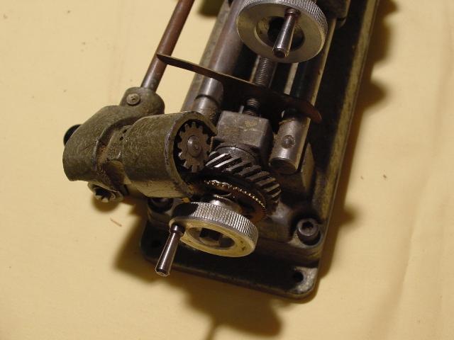
Part 1290 Part Power-feed attachment
Here the little Unimat is being stretched to the limits of its strength and capacity - aided by a belt-driven longitudinal-feed attachment. This was a relatively complex accessory - and beautifully made. At the tailstock end of the lathe a worm and wheel mechanism (covered by a flat plate in the picture) provided a further step-down ratio - the ball-ended engagement lever for this unit can be seen protruding forwards in line with the tailstock.

Tailstock end of the well-made power-feed unit

Drill
Here the milling table is being used to clamp a long, round bar whilst the vertical attachment is used as a high-speed drill.

Part 1080 set up as a  Jig Saw. This useful accessory was driven by an eccentric attached to the spindle nose.

Gear Cutting and vertical
Milling and drilling work

This illustration shows the vertical milling and drilling attachment in position. The headstock and motor drive assembly are removed from the lathe and fastened to the end of a solid steel bar. The bar is then located into and locked in the spigot hole left by the headstock. To provide a vertical feed, the headstock spindle assembly is arranged to slide in and out of the headstock casting, return being by a large coil spring..
The arrangement illustrated shows the maker's dividing head, mounted on the accessory T-slotted milling table, holding a gear which is being generated by a modular cutter held in an arbor on the end of the head


Instruction Books, Parts Books and drive
belts are available for the DB200 & SL1000

Emco Unimat DB200 & SL1000 Accessories

Unimat Home Page  Emco Home Page  Accessories  Earliest Unimat - Photographs 

Mk. 2 & 2A  Photographs  Mk. 2B Photographs  SL1000/DB200 Photographs 

Russian Copy  Unimat Nameplates  Unknown  Motors  Motor Repair  Computer Control

Home-made SL1000  ROWIC - Argentinean Collets  Mk. 4 Photographs

Display Cabinet With Every Known Accessory     

email: tony@lathes.co.uk
Home   Machine Tool Archive   Machine-tools for Sale & Wanted
Machine Tool Manuals   Machine Tool Catalogues   Belts   
Books   Accessories