email: tony@lathes.co.uk
Home   Machine Tool Archive   Machine-tools Sale & Wanted
Machine Tool Manuals   Catalogues   Belts   Books  Accessories

Schaublin 102-VM Lathe

A Operator's & Maintenance Manual is available for the 102-VM

Schaublin 102-VM Lathe Photographs

102-VM Accessories   102VM Photographs    102-VM Collets

Schaublin Home  Model 65 & 70 Lathes   Model 90 & 102 Plain Lathes
 
102N-VM   102 Accessories   102 Stands and Drives   Schaublin SV9A Cam-forming Lathe
 
     120-VM   Schaublin 125 Lathe   SV-130 & SV-150  135 Lathe 

Schaublin Millers   Schaublin Tapping Machine 

If you have a Schaublin machine tool of any kind - or special attachments, etc. -  that
you would like to see displayed in the Archive, please do contact the writer

A design dating from the mid 1930, the 102 mm x 450 mm (4" x 17.75") Schaublin 102-VM lathe is the most frequently encountered of the company's smaller screwcutting models. Of ingenious (if complex) execution, it was built from high-quality materials and became a worldwide favourite in toolrooms and precision workshops. Today, although the original 102-VM lacks the extra capacity and the user-friendly features found in precision lathes of later design (such as the Monarch 10EE and especially the Hardinge HLV), it remains very sought-after, always commands a high price and, if looked after, can be regarded as a sound investment. An unusually wide range of (expensive) accessories was available that allowed the lathe to perform numerous precision machining, milling and grinding operations.
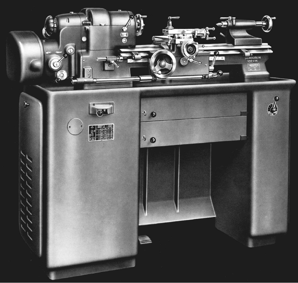
As standard, the original 102-VM lathe was fitted to a compact but massively heavy (274 kg/604 lb) cast-iron one-piece stand and chip tray with either one or two centrally positioned lockable storage drawers. Available in several configurations to suit toolroom or production work, it was normally supplied with the motor mounted on a hinged bracket that could be lifted by a foot pedal to ease speed changes together with a quick-action belt shifter (part No. 102 VM-80.200) and a strange (but effective) knee-operated start, stop and reversing switch (No. 102-80.300). Operation of the speed-change mechanism took a little practice to master - the technique being to use both it and the motor-lift pedal simultaneously. 
With large, integral feet at each end the bed was similar to that used on the plain-turning 102 lathes but with carriage ways formed as extensions to the bed's front and back walls (covered with screw-on sheet metal covers) - the front of V-form and the rear rectangular. As a full-length central T-slot ran down the middle - and traditional bevelled sides were employed - the bed could also mount many of the plain lathe's accessories.
Available with a choice of headstock spindles, the one fitted as standard (Part No. 102 VM-27) had a 20-mm bore and a maximum collet through capacity of 14.5 mm. The Type W20 collets used were 19.7 mm in diameter, 73 mm long and with an unusual buttress-form thread of 0.780" x 1.666 mm pitch - a type also found on some Jones and Shipman grinding machines. A word of warning - confusion can arise because not all collets marked W20 are identical - some were made especially for Swiss Mikron lathes and these are 19.75 mm in diameter, 80 mm long and with either a 2.0 mm or 1.25 mm pitch thread. As an alternative, but at extra cost, a spindle was available with a 25-mm bore and its collet capacity increased to a more useful 19 mm (W25-type). For collet closing all spindles could be fitted with either the standard draw-in screw tube or a number of different quick-action lever closers, though use of the latter precluded the fitting of a bolt-on headstock dividing attachment. Although a screw-thread nose was standard on both sizes of spindle, the customer could choose (but on the smaller-bore spindle only)  a rarely-found "miniature" version of the popular "D" camlock, a size D1-2" - this fitting being used on many examples exported to the United States. The screw-type spindle noses were M37.6 x 3 mm pitch with the early type just screwing on but later examples being fitted with a clamping ring, locked by a hexagon-socket head screw, to prevent nose fittings from unwinding when the lathe was run in reverse. At the front the spindle ran in a precision, double-row cylindrical-roller bearing and at the rear in a pair of selected precision ball races. Although Schaublin must have been satisfied that the standard headstock assembly would perform more than adequately they did offer, at extra cost, a set of "ultra-precision" bearings.  However, although all examples seen by the writer have been equipped with anti-friction bearings, it is believed that early versions of the 102-VM, constructed before the 1940s, had a different arrangement and one similar to that used on the less highly stressed 102 plain lathes. If so, the spindle would have run in a pair of parallel-bore bronze bearings tapered and slotted on their outside and with a thread on the end - a similar arrangement being used on a variety of contemporary small lathes including Mikron (and quite ordinary Drummond B and M-Types of English manufacture). Slotted nuts on the threads, turned by a thin C-spanner, drew the bearings into tapered seats and compressed them slightly, so setting the running clearance. Longitudinal thrust was taken by a ball race just behind the spindle nose. It is essential to use only the highest-quality oils in a Schaublin headstock and, although it is sometimes difficult to arrive at a modern equivalent to the older types specified in the handbooks (for example on the round-head lathes: "
a good quality mineral oil with viscosity of 2.5 degrees Engler at 50 degrees C", or the special "Kluber" grease used for the angular-contact bearings in the later square-head machines) most lubricant manufactures run web-based technical departments that will advise on an equivalent if they are supplied with the appropriate data. A dog-clutch engaged, 5 : 1 ratio single-lever-operated backgear was fitted (although the specifications sheets hint that this may have been omitted on request) and lubricated by an oil-bath with a sight-glass level indicator. Together with the standard 2-speed (750 and 3000 r.p.m.) 3-phase electric motor with a 2-step V-pulley drive to an intermediate countershaft - and a smooth-running 3-step flat-belt final drive to the spindle (maker's specification 102 VM-8.100) the headstock gearing produced a theoretical set of 24 spindle speeds. However, as some speeds were duplicated, the number of significantly-different ones was 18: these were: 40, 55, 70, 90, 120, 150, 170, 210, 270, 350, 450, 580, 840, 1100, 1400, 1800, 2300, 3000 r.p.m. Also known to have been available, but not listed in the catalogues and fitted to only a few machines, was a 3-speed motor - though no details of the Schaublin-approved specification appear to have survived.
Continued below:


1954 version of the Schaublin 102VM Precision Toolroom lathe

Continued:
Surprisingly, no power cross-feed was fitted but, as some compensation, the drive from headstock to carriage could be routed through either the changewheels or via a 4-speed V-belt drive. The drive could be switched instantly from gear to belt by a lever, just to the right of the changewheel cover, and the belt swapped from groove to groove by unclamping the eccentric boss that carried the top pulley. On early models the pulleys were left exposed behind the headstock but later were encased first in a rather crude sheet-metal cover and then inside a neat, hinge-open aluminium housing. The pulley system was driven by worm-and-wheel gearing from the headstock spindle and gave, in combination with the 26 changewheels provided, an unusually wide range of feeds and threads: metric pitches from 0.25 to 6 mm and English from 4 to 60 t.p.i. could be generated together with carriage feed rates from 0.016 to 0.117 mm (0.0006 to 0.0045") per revolution of the spindle. The large number of gears also allowed for a coarse feed to be set up and left in place - with the V-belt drive then being reserved for ordinary and fine feeds.
Changewheels ran on large-diameter studs retained with quick-change slotted washers and were housed under a cast-aluminium cover with a hinge-open door - on the inside of which was a particularly clear screwcutting chart. The robust, buttress-thread, 4mm pitch leadscrew, used for both screwcutting and the sliding feed, was a massive 40 mm in diameter and ran underneath the bed, down its centreline, where it was completely protected from swarf and dirt.
Sliding on an inverted V-way at the front, and a flat way at the back, the massive carriage assembly had, in effect, aprons at both front and rear so forming a closed loop around the bed. The long, rigidly supported and automatically lubricated leadscrew clasp nut (the "
chaser" in Schaublin language) was positioned directly on its centre line and - ensuring the shortest forces path between the two - exactly under the cutting tool. The mechanism inside the apron was lubricated by an oil bath that was also fed to the clasp nuts - and provided with sight-glass level window.
Continued below:

A section through the 102VM bed (towards the headstock) that
also shows, to scale, the huge size and location  of the leadscrew

Continued:
Control of the carriage traverse was shared amongst three levers: two pivoted from the right-hand face of the apron - with one to engaged the drive and the other to provided instant reverse - whilst the third lever, on the front face of the apron, was arranged to flick the drive out of mesh. The lever-operated carriage disengage mechanism was extended to include knock-off buttons - protruding from each end face of the apron - that allowed the drive to be automatically and instantly released in either direction. The disengage stops slid along and bolted to the front of the bed and, although fitted with fine-adjustment screws, these were not, unfortunately (as they were on a Rivett 608), provided with micrometer collars.
As might be expected, the compound slide was beautifully engineered with a particularly smooth feel to its movements. The cross slide was of the full-length type - to give maximum support to the cutting tool and even out wear on the ways - and was fitted with a large-diameter, finely-engraved, easy-to-read zeroing micrometer dial. The cross-feed screw was supported in a bearing at its rear and, at the front, ran through a ball race arranged, in a patented way, so that: "
no dismantling was required to take up axial and radial play". The upper part of each edge of the cross slide was machined with a dovetail to allow the fitting of a travelling steady. The top slide could be rotated 180 degrees either side of central and (on later versions only) engraved with a linear measure along its front edge complete with adjustable pointer. A variety of toolposts was available from a simple so-called "American" unit to expensive quick-set and even quick-withdrawal types, the latter to help with repetition or high-speed screwcutting.
Reported variously with either a 2-degree taper socket, or a Jarno fitting, the tailstock can be a cause of some frustration - unless a selection of suitable centres and other fitting chucks come with a second-hand lathe. However, GEPY in Switzerland (http://www.papaux-gepy.ch/gepy_quills.htm) still make a range of rotating and other centres with a 2-degree taper. It is possible to machine the barrel out to a No. 2 Morse - but the material is hard (probably a carbon steel), and great care is necessary to get everything in line. It is not a job for other than a professional machinist - or a very experienced and confident amateur. Tailstocks could be had with screw, simple lever and capstan-handle driven rack-feed barrels - though the latte, being very expensive, is rare. A later incarnation of the 102VM was the 102N-VM, an updated machine with distinctly angular styling built during the 1970s and 1980s
A standard 102-VM was approximately 69-inches (1520 mm) long, 21-inches (540 mm) deep and weighed around 1345 lbs (610 Kg.).
Pictures of a restored 102VM, 102VM Collets and 102VM Accessories ..

The massive, 40 mm diameter leadscrew was engaged by an exceptionally long single-sided nut.


A picture showing some significant features of the 102VM: the carriage ways carried on the front and back walls of the bed (with long sheet-metal swarf guards); separate bevelled-edge ways with T-slot location for the tailstock; carriage controls for engaging and instantly reversing its feed; a full-length cross slide; long-travel top slide with a ruler-engraved edge and twin T slots (to allow maximum versatility when mounting tools and attachments) and the large-diameter cross-feed micrometer dial. The pulleys at the back of the headstock provided a range of fine feed to the carriage independent of the screwcutting changewheels.

The clean lines of standard headstock type 102-VM-27 with hand-operated collet drawbar, a 5 ; 1 reduction gear with single-lever control and a gearbox for the selection of gear-driven or belt-drive feeds. The three rings of indexing holes in the headstock pulley were engaged by a pointer mounted on a swinging bracket.

Instead of the 13 or so changewheels normally supplied with a small lathe the 102 was issued with 26, so enabling an enormous variety of metric (0.25 to 6 mm) and English (4 to 60 t.p.i.) pitches to be generated. The gears, running on studs with quick-change slotted washers, were housed under a cast-aluminium cover with a hinge-open door on the inside of which was a particularly clear screwcutting chart.


Control of the carriage feeds was split between three levers: on the right-hand face of the apron one control engaged the drive, another provided an instant reverse whilst a third, on the front face of the apron, was arranged to flick the drive out of engagement. The mechanism connected to this lever was extended to buttons - protruding from each end face of the apron - to allow the drive to be instantly knocked off in either direction by stops mounted on the front bedway

Surprisingly, no power cross-feed was fitted but, with the drive from headstock to carriage through both changewheels and V-belts, the sliding feeds were thoughtfully arranged to provide the operator with the best chance of being able to select exactly the right feed for any job. The changewheel drive, besides its use for screwcutting, was also set up to provide a range of coarse feeds with the V-belt drive for ordinary and fine feeds. The drive could be switched from one to the other by a lever just to the right of the changewheel cover.


A Operator's & Maintenance Manual is available for the 102-VM

Schaublin Home  Model 65 & 70 Lathes   Model 90 & 102 Plain Lathes
 
102N-VM   102-VM   102 Accessories   102 Stands and Drives   Schaublin SV9A Cam-forming Lathe
 
102-VM Accessories   102-VM Collets  120-VM   Schaublin 125 Lathe
 
102VM Photographs  120-VM    SV-130 & SV-150  135 Lathe 

Schaublin Millers  102N-VM Photographs   Schaublin Tapping Machine

Schaublin 102-VM Lathe

If you have a Schaublin machine tool of any kind - or special attachments, etc. -  that you would like to see displayed in the Archive, please do contact the writer
email: tony@lathes.co.uk
Home   Machine Tool Archive   Machine-tools Sale & Wanted
Machine Tool Manuals   Catalogues   Belts   Books  Accessories