|
Home Machine Tool Archive Machine-tools Sale & Wanted Schaublin 90 & 102 Plain Lathes for Bench & Stand Mounting A complete data pack is available for the 90 and 102 Plain Lathes Schaublin Home Model 65 & 70 Lathes Model 90 & 102 Plain Lathes |
||
|
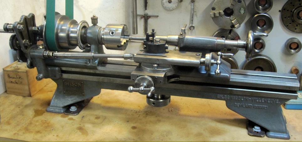
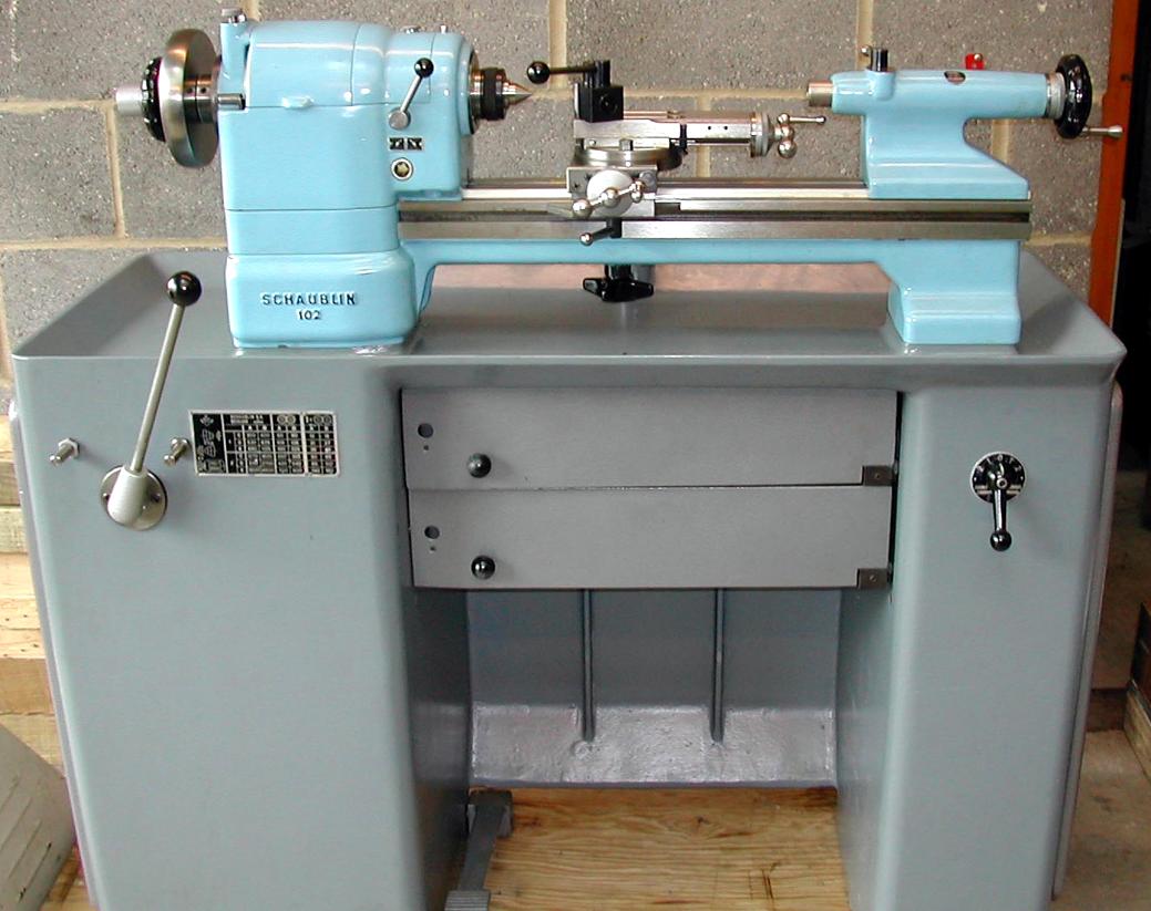
Originally sold in two centres heights as the SV90 and SV102, the latter was to become the best known and most widely used of the company's precision plain-turning (non-screwcutting) lathes. Although the SV90 had disappeared from the maker's lists by 1946, the 102 was constantly modernised (though in reality this was just rectangular styling of the main castings and accessories and the option of anti-friction headstock bearings) and is still being made today (2015). All models of Schaublin precision plain lathe were designed so that a customer could order one or more types of bed and then mount on each, or subsequently interchange, a variety of different headstocks, tailstocks and slide rests. In order for this to happen it was necessary, of course, for all components to be made to such a high standard of accuracy that each was absolutely interchangeable, aligned perfectly and would allow, for example, a precision plain-turning "toolmaker's" lathe to be instantly converted into a production machine by simply removing the compound slide rest and bolting in its place a rotating capstan toolholder. This ease of conversion was achieved not by building complete machines in batches and then dismantling - but by concentrating on the accurate gauging of the sub-assemblies where limits of 0.001 mm were the norm. Even if the factory received an order for a lathe built to a particular specification the required elements were just drawn from the stores, assembled, checked to limits in excess of those proposed by Schlesinger, packed and dispatched; the company claiming that no "fitters" were needed to scrape or otherwise modify parts. A disadvantage of this system was the need to carry in stock, at some expense, a cushion of built-up sub-assemblies ready for dispatch - and if you were one of the world-wide network of Schaublin agents you too were required to hold a certain number of the more common parts for instant delivery. As confirmation of this accuracy, in 2006 a used faceplate was brought over from Switzerland for a 102. When fitted it had a run-out better than 0.0001", yet the part and the lathe had been manufactured 20 years apart. For the popular 90 and 102 lathes every year of manufactures (until recently) has seen Schaublin list beds in short ("Type 1a" 600 mm long) and standard ("Type 1" 900 mm long) versions, with feet at both ends, and another short-bed version ("Type 1b" 650 mm long) with a single foot and cantilever construction. As lathes bolted to cast-iron chip trays - or mounted on self-contained underdrive stands - became more popular Schaublin widened the range to include models with beds specifically adapted for these purposes, the earliest version for an underdrive model being designated bed "Type 1c" at 900 mm long. Until the 1980s, when the length was increased to 1000 mm, the standard "Type 1" bed remained faithful to the 900 mm figure - a specification that gave between-centres capacities of 300 to 425 mm depending upon the particular combination of headstock and tailstock fitted. |

|
Continued: |

|
Toolmakers' Lathe Model TO-102 for overhead or rear drive, draw-tube collet closer for W20 or W25 collets and screw-feeds to both compound slide and tailstock |

|
Second-operation Lathe TL-102 for overhead or rear drive with lever-action collet closer for collet types W20 and W25 and a lever-action tailstock |

|
Turret lathe TR-102 for overhead or rear drive with lever collet closer for (collet type F27), spindle nose retaining nut and nose cap, 6-position bed-mounted capstan unit and lever-action cut-off slide with front and rear toolposts |

|
Early unguarded Type 102-96 countershaft unit termed an "Individual Drive" by Schaublin. This could be mounted behind the lathe, underneath it, on the wall, ceiling or even the floor. The drive ratios from motor to countershaft were arranged at 1:1, 2:1 and 3.5:1 and the head could be had with either the normal 3-step cone pulley or, for heavy-duty production work, a 2-step. Another option was a 2-step V-belt drive on the motor to countershaft section. In the early 1950s the unit was available with 4 motor options, all supplied complete with switch: |

|
|

|
|

|
|

|
|


|
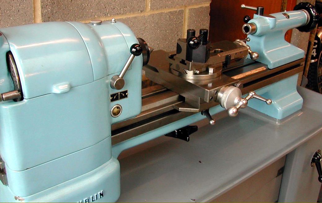
and the very desirable (and much-improved) tailstock with the "peep-though" glass to read the ruler engravings and plastic handwheel |


|
Schaublin Home Model 65 & 70 Lathes Model 90 & 102 Plain Lathes Home Machine Tool Archive Machine-tools Sale & Wanted Schaublin 90 & 102 Plain Lathes for Bench & Stand Mounting |
||