 |
 |
 |
 |
 |
 |
 |
 |
 |
 |
 |
 |
 |
 |
 |
 |
 |
 |
 |
 |
 |
 |
 |
 |
 |
 |
 |
 |
 |
 |
 |
 |
 |
 |
 |
 |
 |
 |
 |
 |
 |
 |
 |
 |
 |
 |
 |
 |
 |
|
|
|
|
|
|
|
|
|
|
|
|
|
|
|
|
|
|
|
|
|
|
|
|
|
|
|
|
|
|
|
|
|
|
|
|
|
|
|
|
|
|
|
|
|
|
|
|
|
|
|
|
|
|
|
|
|
|
|
|
|
|
|
|
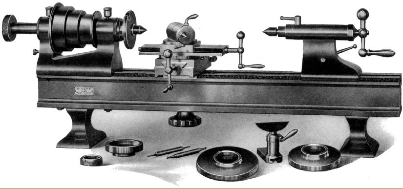
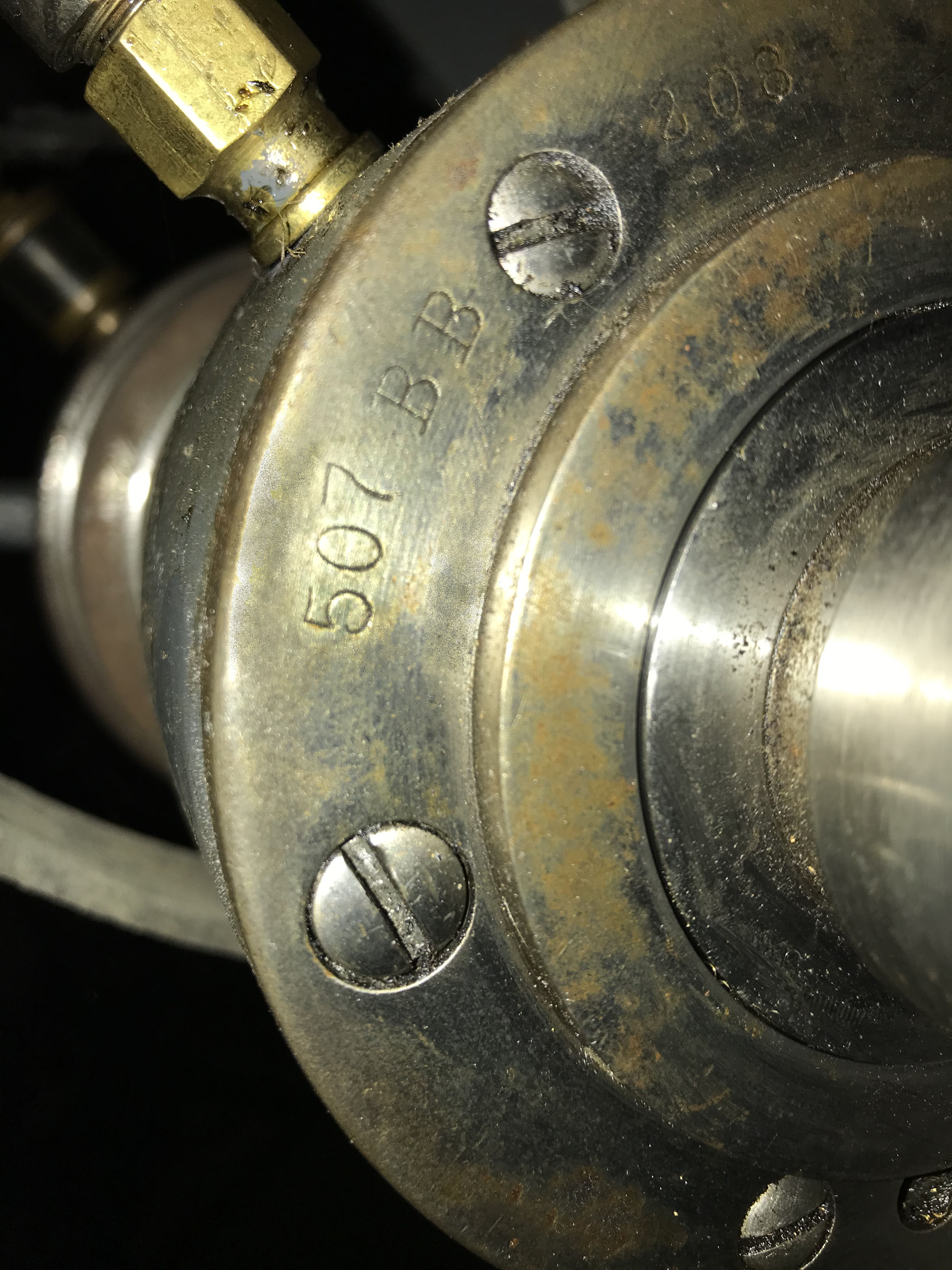
Having longest production run of any Rivett lathe except for the famous 608, the "500" Series was made from just after the end of WW1 (1918) until 1953. Of very similar design, the Rivett Types 504, 505 and Type 507 Junior lathes were distinguished by price with the plainly finished 507 being much less expensive than the cosmetically superior 504 and 505. The latter two lathes were also offered with a choice of five headstocks with either plain or ball-race bearings; although the 507 is usually being found with plain bearings, there was a small number - listed as the Type 507BB - offered with anti-friction bearings. Damming it with faint praise, the makers described the 504 as: A plain Precision Bench Lathe of medium weight, suitable for average tool room work. Swing 8", distance between centres 18", bevelled edge guiedways; equipped with Rivett Type Compound Slide Rest. The 505 was separated from the 504 by the explanation: A Plain Precision Bench Lathe of heavier construction than the No. 504, suitable for Tool Room work and light manufacturing. Swing 8", distance between centres 18", bevelled edge guideways; equipped with Compound Slide Rest with Rocker Tool Post. All types were available equipped as precision bench lathes for one-off work by a skilled machinist or, fitted with the appropriate accessories, as a repetition capstan (screw machine) for the manufacture of small parts. Because the lathes had identical bed ways, most of the very wide accessory range from the 504 and 505 could also be mounted on the 507 - with many of them being modelled on those made (for many decades) for the 8" Precision Lathe and 608. Launched during the 1930s, the three lathes faced strong competition in a crowded market with a number of other American makers - including Hardinge, Wade, Stark and Ames* - all offering very similar products.
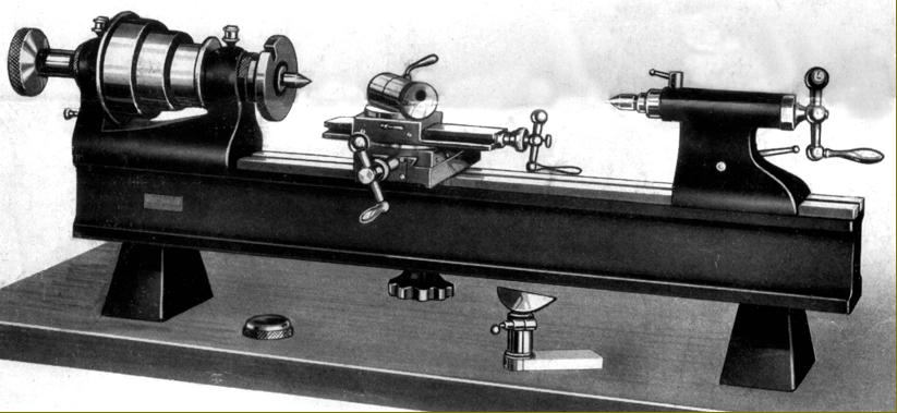
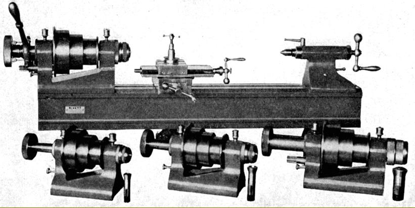
With just one bed available, 38-inches long, the Types 504 and 505 admitted from 16.5 to 19.5 inches between centres, the difference being accounted for by the lengths of the various headstocks; originally five were available: 3NS (9/16" bore spindle; 4NS (11/16" bore); 5NS (15/16" bore); 5C (1.125" bore) and the unusually large 6H (1.25" bore) - the latter dropped in later years. The smaller three all had a 12 t.p.i. Spindle nose, the largest two a 10 t.p.i.--all of USF form. While the plain-bearing heads had a maximum speed of around 2000 r.p.m. (depending upon the particular countershaft used) the ball-bearing units could be made to run as fast as 4600 r.p.m., ideal for smaller parts or the increasingly popular (in the 1930s) tungsten-tipped tools. As with all Rivett lathes, a bewildering variety of stands and drive systems was available, some (being very complex) being much more expensive than the basic lathe. For indexing the outer flange of the largest headstock pulley was drilled with a single ring of 60 holes, with an additional 10 holes provided for a locking pin. One particularly rare version was also offered, the BH-8 with an enclosed headstock (should you have an example, the writer would be most interested to hear from you) The usual very high quality and beautifully finished Rivett-type compound slide rest was used, this time with a choice of either an ordinary rocker toolpost in a T-slotted top slide or a quick-set, 8-inch Precision and 608-type eccentric toolholder.
Continued below:
|
|
|
|
|
|
|
|
|
|
|
|
|
 |
|
|
|
|
|
|
|
|
|
|
 |
|
|
|
|
Rivett 505 Plain Precision bench lathe. Note the deep bed and 608 and 8-inch precision-type quick-set toolholder
|
|
|
|
|
|
|
|
|
Continued:
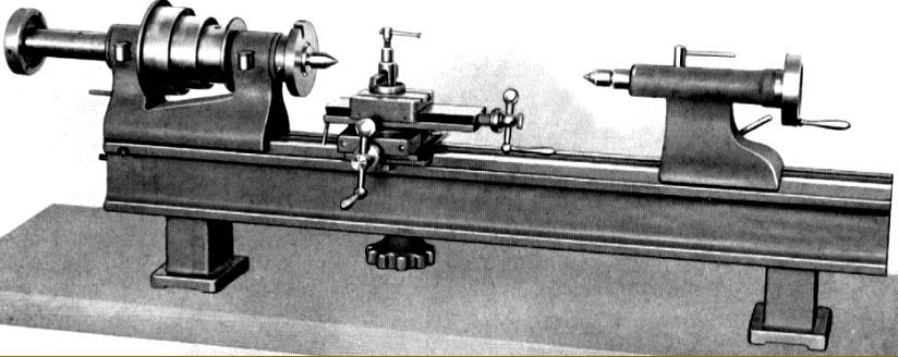
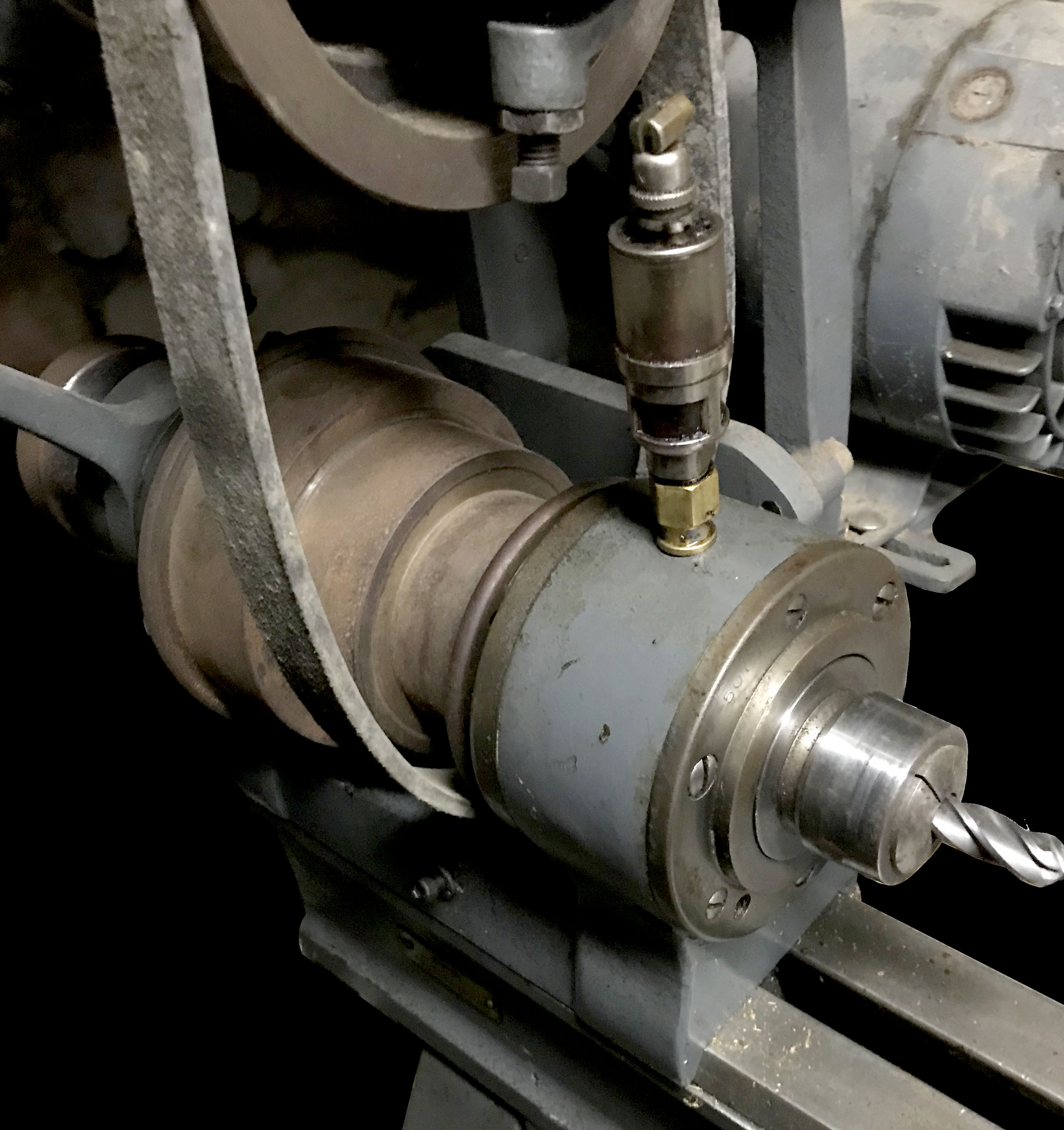
Although relatively inexpensive (at least in comparison with the breathtakingly pricey "senior" lathes in the range) the Type 507 Junior had a headstock of first-class design and execution. Although a Model 507BB was offered with a ball-bearing supported spindle, the vast majority of this type were fitted with plain bearings - these being parallel on the inside and tapered on their outer, so allowing them to be drawn into conical seats and the running clearance set with great accurately. After some time "running in", the tool-steel spindle imparted a hard glaze to the cast-iron bearings shells, after which, providing lubrication was not neglected, the life expectancy could be measured in decades. End float was controlled by a ring screwed into the face of the drive pulley - with simple fibre washers to take the thrust. Instead of a threaded nose, the spindle (made from tool steel, ground all over and hardened on its end), used an external taper with a 5° included angle, 29/32" long and with a diameter of 1.7334" on its smaller end. By this means, fittings such as chucks, back-plates and drive-plates could be mounted with the absolute assurance that they would run dead true. Although the outer taper located and retained the fittings, security was assured by each being fitted with two cone-point screws that bore against a reverse 45° on the spindle end. Fitting and removing items involved the lightest of movements (if heaver, something is amiss) with, as further advantages, easily cleaned parts and the ability to run at high speed in reverse.
Sized to take Rivett No. 7 collets (with a maximum round capacity of 3/4", square of 17/32 and hexagon of 21/32), the spindle was bored through 1-inch diameter - though the collet locating key reduced its maximum clear-though capacity to 7/8". Rather wider than one might have expected at 1.25-inches, the 3-step headstock pulley had diameters of 3", 3.75" and 4.5" with a single ring of 60 holes that could be used for indexing or to lock the spindle when changing nose fittings. Spindle speeds depended upon the particular countershaft employed, but with the standard over-head 2-speed unit ran from 216 through 320, 475, 500, 750 and 1100 r.p.m.
Bed
Made from cast iron with integral feet, the bed followed traditional bench precision lathe practice by having a flat top with bevelled sides and a central slot for clamping bolts that hung from T-slots in the base of the tailstock, compound slide and other fittings. After machining the bottom of the feet, the under surface of the bed and the ends, the casting was left to season to relieve stresses. After several months, the top surface was machined and the bevelled edges scraped by hand, using master gauges, to a perfect alignment. Realising that the lathe would almost certainly be carried on a wooden bench (subject to distortion with changing humidity) the makers cautioned against bolting it down hard, suggesting instead that it was held just firmly enough to prevent movement. They also suggested that sunlight was not allowed to fall on it, a measurable distortion being caused by heat if it did.
Continued below:
|
|
|
|
|
|
|
|
|
|
|
|
 |
|
|
|
|
|
|
The less expensive Rivett 507 "Junior" Precision Instrument and Clockmakers' Lathe. Note parts of the compound slide left "as cast".
|
|
|
|
|
|
|
|
|
|
|
|
Continued:
Compound Slide Rest
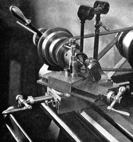
Of conventional design, the compound slide rest was registered by a 4.5-inch long adjustable plate (that allowed for swivel settings) against the front bed bevel and featured the usual long-travel (5") exposed-ways top slide - with the cross slide having 4 3/8" of travel. Both feed screws were of Acme form, 7/16" x 10 t.p.i. (or, optionally, 2 mm pitch) with that on the cross slide completely enclosed, so protecting it from the wearing effects of swarf and dirt. Balanced handwheels were fitted, the locking screws, as on most other Rivett lathes, passing down the stem of the ball end. Micrometer dials (13/16" in diameter) also followed Rivett tradition in being clearly graduated in 0.001" intervals (or 0.02 mm) and fitted with very effective and sensitive knurled-edge locking screws (protruding through the ends of the balanced handwheels) that did not cause the setting to alter when tightened. Long bronze feed nuts were fitted, though (surprisingly) neither could be adjusted to remove backlash. The cross slide was equipped with a screw-adjustable rear stop (that could be transferred to the top slide) to aid threading and repetitive production work. The top slide, locked by an easily-set eccentric clamp, had the normal Rivett-pattern bevelled face carrying degree markings, but in this case only engraved in sets of 45° each side of zero. However, three extra reading lines were a provided that allowed the full 360° of swivel to be read at any position. As a sop to economy, instead of the expected eccentric, quick-set toolholder, an ordinary rocker type was fitted (known in Europe as an "American Type") held in a T-slot, and able to take an Armstrong or similar brand of toolholder up to 5/16" wide and ½" deep.
Tailstock
Not able to be set over on a separate base for taper turning - the long-travel top slide provided that function - the tailstock casting was arranged with a deep sweep at the front to provided sufficient clearance for the top-slide screw handle to clear when working close to the headstock. With 33/8" of travel, the 1-inch diameter spindle was in tool steel, hardened and ground, and ran in a hole honed to a perfect fit. Unfortunately, instead of a standard Morse or even Jarno, the spindle had Rivett's own 3° (included) taper; a specification that, although it must have done wonders for the sale of tailstock attachments, condemned subsequent owners without the right fittings to endless frustration.
Stands
Long a producer of sophisticated (if very expensive) stands, the ones available for the 505 and 507 were virtually identical to those offered for the 608, 715 and 918 models, though fewer in number and variety. For heavy-duty industrial use the makers recommended the:
Oil Pan Mounting Stand with Overhead Drive.
Intended for use with either a bench precision or capstan lathe, this was a very sturdy, all-cast-iron affair with a deep and strong chip tray attached to the back of which was a pair of metal uprights carrying a standard 2-speed Rivett countershaft. When used as a centre lathe, the assembly often included an auxiliary drive to power toolpost and bed-mounted grinding and milling attachments.
Oak Cabinet with Overhead Drive
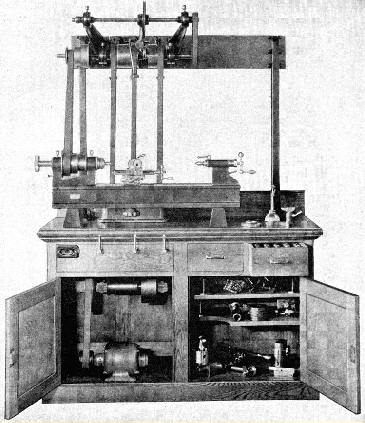
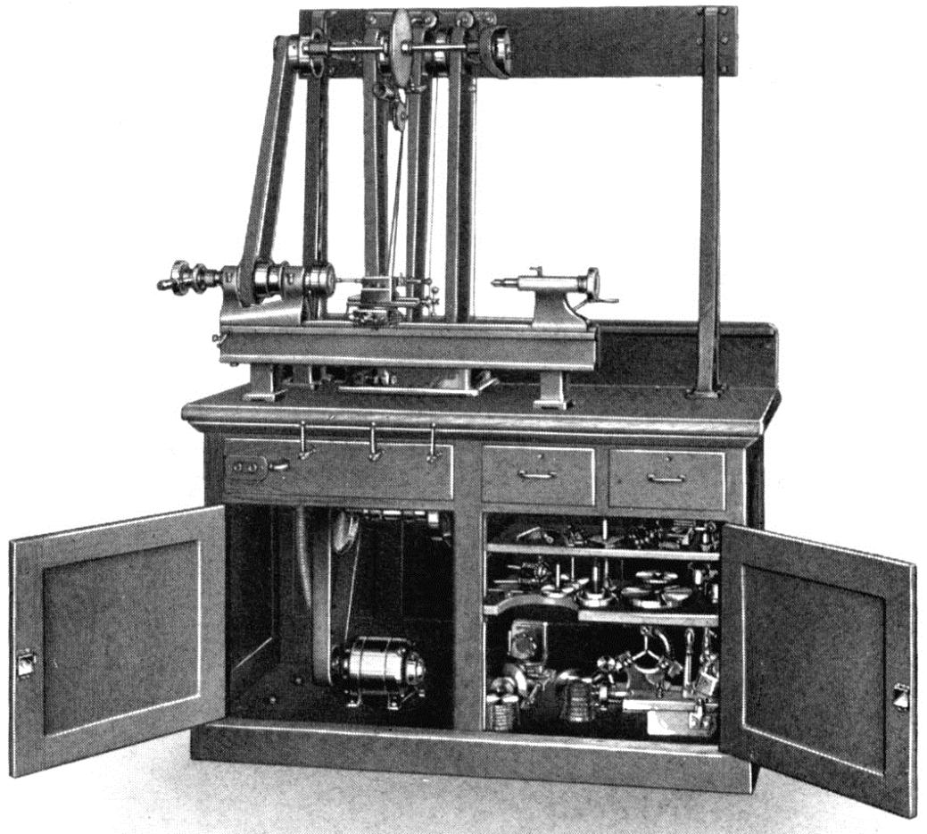
Although fitted with an overhead countershaft, speed control (by belt shifting onto fast-and-loose pulleys) was by three hand levers arranged conveniently along the front face of the stand. This assembly could be fitted, if required, with an auxiliary drive to power toolpost and bed-mounted grinding and high-speed milling attachments.
Oak Cabinet with Horizontal Safety Drive
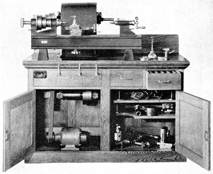
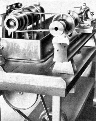
Another version of the oak cabinet designed, as the title suggested, with safety in mind - the drive being enclosed on its rearward run.
Overhead Countershaft Drive on Unit Bench.
A complete 505 and 507 drive system with workbench space, pedal-selected speed change and an auxiliary high-speed grinding and milling drive. Although Rivett supplied the complete countershaft drive unit, a pair of cast-iron countershaft supports (39.5-inches high) a pair of pressed-steel legs (maximum distance apart was a recommended 8-feet) foot treadles, an all-welded 18" x 16" steel drawer assembly, a cast-iron belt guard (just visible in the picture above below the bottom line of the bed) and other mechanical parts - they did not offer any of the woodwork, this had to be obtained locally and made up in-house. A particularly well-thought-out system, with as many as 24 speeds, the all-ball-bearing countershaft was carried on neat, cast-iron uprights attached to the bench with spindle speeds selected by either hand levers or foot pedals. The system could also be fitted with a built-in drive to power toolpost-mounted accessories. With a working space to the right of the lathe, the assembly was intended for use in laboratories or toolrooms where space was needed for tools, small parts and sub-assembles to be laid out and a trail fit of components made. However, despite all these conveniences, by the 1940s this type of drive arrangement was beginning to look distinctly old-fashioned.
Continued below:
|
|
|
|
|
|
|
|
|
|
|
|
|
 |
|
|
|
|
|
|
Later Type 505 showing the four headstocks then available (down from the five on its introduction)
|
|
|
|
|
|
|
|
|
Continued:
Accessories
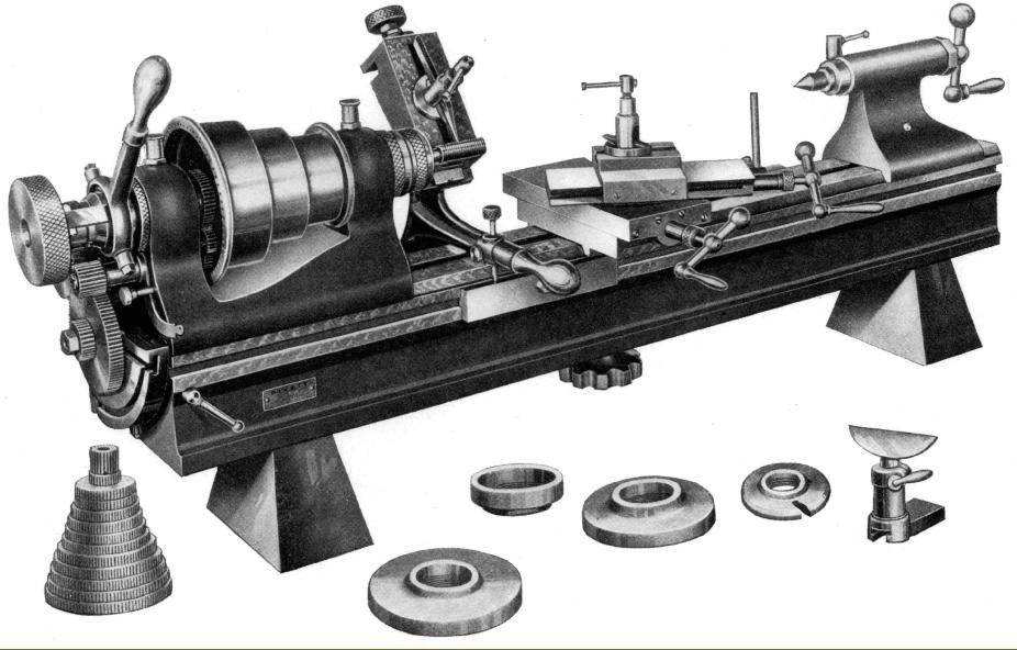
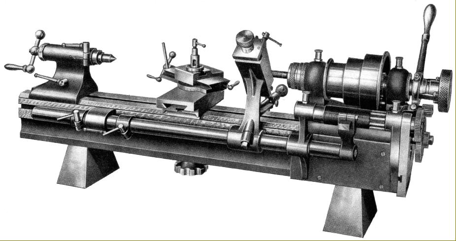
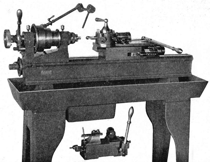
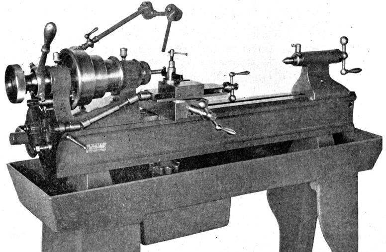
In addition to the usual wide range of collets, collet closers and centres, the expected T and triangular rests in various sizes (hinged and plain) for hand work, drive dogs, fixed and travelling steadies, a faceplate with radial T-slots, a saw table and a slotting unit, Rivett also offered a number of more advanced extras for both the 505 and 507. Amongst these more expensive items was a complete outfit to transform the lathe into a hand-operated capstan unit and an unusual design of milling attachment, almost certainly unique to Rivett, that bolted to the bed in place of the compound slide rest. The unit consisted of a baseplate on top of which was a screw-controlled longitudinal slide able to be moved through 1.125" and swivelled through 360°. Mounted on the base and arranged vertically was a casting shaped to accept the ordinary compound slide rest (and indeed, other bed-mount fittings). Whilst the assembly had a wonderfully varied number of movements its usefulness was somewhat diminished by the lack of a full-sized T-slotted table (as available for example for the Type 918) - its work-holding being restricted to the twin T-slots of the top slide. In compensation the makers did offer a special angle-plate (termed an Angle Iron by Rivett) and a small machine vice. Screwcutting was also available, but only of the changewheel-to-the-top-slide type - an expensive chase-type screwcutting unit - so useful for threading delicate components in softer material - not being listed. However, one very rare version of the 505 did carry chase screwcutting, the 606, but this must have had a very limited production run for it only appeared (so far as is known) in one sales catalogue.
One important accessory - and a unit common to this class of lathe - was the Universal Grinding Attachment, a device that allowed the lathe to be pressed into use as small cylindrical grinding or honing machine for internal, external, parallel and taper work. Supplied complete, ready for mounting on the lathe bed, the assembly comprised a base plate, fitted with a 5-inch travel slide that could be swivelled through 360°. On top of this was a bearing housing carrying a hardened, ground and lapped spindle (with 2.5-inch of hand-fed travel) that could be hinged clear of the work (for measurement and inspection) and then dropped back into position without loosing the previous setting. The spindle was formed on its end with a Pratt & Whitney No. 4 taper to mount grinding wheels and, using a 3-step pulley with drive from a separate motor mounted behind the lathe bed, could be made to run at 6000, 8000 and 10,000 r.p.m. in reverse direction to the lathe spindle. With lathe and grinding spindle both on top speed, an effective maximum r.p.m. of 35,000 r.p.m. could be obtained, a figure high enough for all but the very smallest of work.
Also listed for the 505 and 507 - but rarely found on used examples - was an attachments for the relief of cutters complete with its own drive pulley, gear set and a universally joined and splined shaft drive to the top slide.
This page Continued here and a Rivett 504 photographic essay here
|
|
|
|
|
|
|
|
|
|
|
|
|
|
|
|
 |
|
|
|
|
|
|
|
|
|
|
 |
|
|
|
|
|
|
Rear view of the Rivett 606 chase screwcutting lathe
|
|
|
|
|
|
|
 |
|
|
|
|
|
|
Rivett 505 set up as a turret lathe with a lever-action collet closer, self-indexing turret head, cut-off and forming slide (foreground) and mounted on an all-cast-iron stand and chip tray with coolant pump and piping
|
|
|
|
|
|
|
|
|
|
|
|
 |
|
|
|
|
|
|
Rivett 505 with changewheel-driven screwcutting attachment
|
|
|
|
|
|
|
 |
|
|
|
|
|
|
Oak Cabinet with Overhead Drive A Type 505 on the maker's oak cabinet with warp-free laminated top. Although fitted with an overhead countershaft, speed control (be belt shifting onto fast-and-loose pulleys, was by three hand levers arranged conveniently along the front face of the stand
|
|
|
|
|
|
|
 |
|
|
|
|
|
Oak Cabinet with Overhead and Auxiliary Drive. A Type 507 Junior on the oak cabinet
|
|
|
|
|
|
|
|
|
|
|
 |
|
|
|
|
Seldom found a Rivett 507 Junior with the ball-bearing headstock Type 507BB
|
|
|
|
|
|
 |
|
|
|
|
 |
|
|
|
|
|
|
Oak Cabinet with Horizontal Safety Drive - another version of the oak cabinet designed, as the title suggested, with safety in mind
|
|
|
|
|
|
|
 |
|
 |
|
|
|
|
|
|
|
Two views of the Horizontal Safety Drive countershaft
|
|
|
|
|
|
|
|
|
|
|
|
|
|
|


