|
Home Machine Tool Archive Machine-tools Sale & Wanted 504, 505, 507 & 606 Precision Lathes 715 Lathe 918 Lathe 1020/1030 Toolroom Lathes 1020R Toolroom Lathe Rivett Watchmaker's Lathes Rivett Factory Rivett Millers |
||
|
Edward Rivett had a long background in the watch lathe and tool industry before he turned his hand to manufacturing larger precision machine tools. Born in 1851 near Montreal, in Canada, it is thought that he might have served time as an apprentice in Switzerland - obviously in the watch or other precision industry. He took out his first patent (of around 30 to be registered in his name) in 1880 when he was working for C.A.W. Crosby, a successful Boston jeweller and watchmaker; this partnership developed to the extent that, in 1884, the pair registered the Faneuil Watch Tool Company with Rivett as General Manager and Crosby as Treasurer. From a modest workshop the business expanded until it occupied a newly-built factory, 125 feet long and with 150 windows, overlooking the Charles River in Brighton, Boston. In 1890 the partners could see the opportunities in diversifying from a sole reliance on watch lathes and their associated tooling and began to expand their product range to include, first, the No. 4 Precision Bench Lathe, a small range of high-precision bench milling machines, a made-to-order, 3-ton, three-spindle vertical-milling machine, then various grinders and other sizes of bench lathe, including the No. 3 and No. 4 and the wonderful 8-inch Precision. In 1903, to (partially) reflect the company's change of direction, it was named the Rivett Lathe Manufacturing Co.. |
|
Rivett 608 precision lathe 4.5" x 18" as produced in the early 1940s. This particular model, on non-height-adjustable "pyramid" feet, was intended to be driven by a rear-mounted countershaft. |
|
On some forms of maker's stand the lathe bed, to prevent it being twisted by an uneven installation, was supported at the headstock end by placing a ball bearing under the front edge, and another under the rear - whilst a single ball was positioned in the middle of the bed at the tailstock end. Various forms of overhead auxiliary drive were also available, designed to power a range of grinding, traverse-milling, threading and drilling attachments, etc. |
|
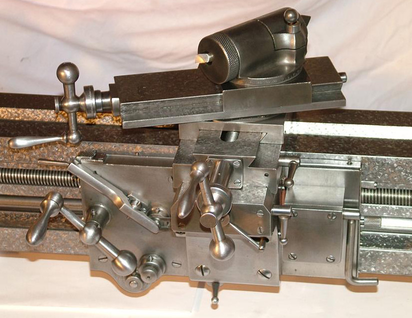
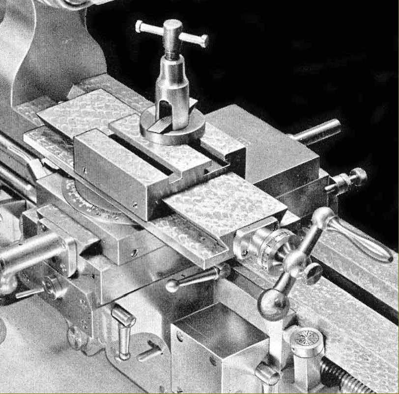
Typical of the well thought-out features included in the design of the Rivett 608 was the fact that no tools, apart from a chuck key, were required to operate it; a slender lever (it can be seen on the end of the cross-slide base) released the compound slide rest and it could then be instantly repositioned, or slipped off to be replaced by a variety of beautifully-made accessories including a vertical milling slide, hand-tool rest, saw table or indexing, slotting, ball-turning and relieving attachments. |
|
A variety of toolposts was offered including this design, first seen in the 1880s, where a round cutting tool was clamped into an lever-locked eccentric mount which could then be rotated to adjust the tool's height and rake. This type of toolpost appears to be the one fitted as standard to all 608s exported to the UK. |
|
|
||
|
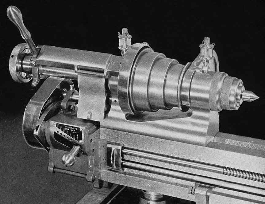
On lathes with a screwcutting gearbox the lever-operated collet closer had to be mounted at the end of a long extension tube. |
||
|
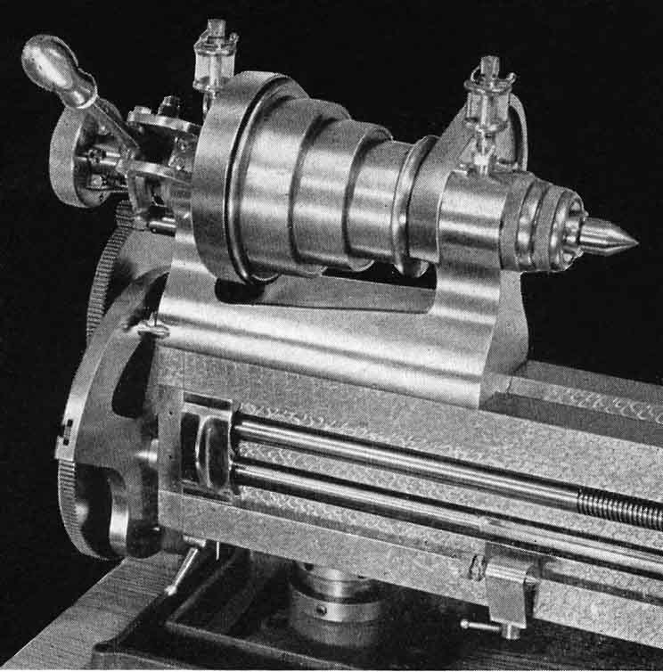
One the changewheel-equipped lathe the lever-action collet closer assembly was mounted directly on the end of the headstock. Clearly visible in this picture is the jacking screw incorporated in the bed foot. |
|
|
|
|
|
|
||
|
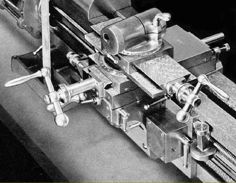
Tailstock spindle micrometer dial - a most useful fitting that took other makers of similar lathes many years to fit. |
Steel Knee-hole Cabinet. An underdrive stand that was the most modern looking to grace a Rivett 608. The motor countershaft unit, which ran entirely on ball bearings, was contained within the base on its own adjustable mounting plate. When fitted to this stand the 5C collet fitting headstock spindle was driven by a double V belt from a two-speed motor; a total of twelve speeds was available: 45, 60, 85, 100, 140, 195, 300, 405, 565, 680, 935 and 1290 r.p.m. - though one catalogue has the maximum at 1500. Machines fitted with English 50 Hz 1425 rpm motors would have run as much as 25% slower - unless given a more powerful motor and correspondingly larger drive pulley. A version of this lathe is shown lower down the page in colour photographs.
Oak Cabinet with Horizontal Safety Drive. This was a substantially-constructed stand, built from quartered wood with a 5-ply laminated top of 57" long and 24" wide and fitted out on the inside for the storage of accessories and collets. Fitted with a single-speed, 1700 rpm motor, twelve spindle speeds were available. To reverse the direction of rotation the motor could be left running and a "crossed-belt" mechanism operated.
|
Oak Cabinet with Speed Box Drive A stand similar in size and construction to the belt-driven underdrive stand this version was fitted with the "Speed Box" used on the cast-iron and open-frame stands (shown below). The drive system involved the use of a beautifully built two-speed gearbox held within the cabinet and driven by a single V-belt from a motor carried on a hinged plate behind it. The gearbox contained upper and lower shafts, each carrying pairs of helical-cut gears, of different ratio and arranged so that the two shafts were connected by the gears in constant mesh. Either pair of gears could be selected through a two-way, multiple steel-disc clutch operated by a hand lever moving through a lateral quadrant (marked Rivett in the picture). The unit incorporated an automatic brake, activated when the lever was moved to its spring-loaded central position. The gearbox, in which all moving parts were dynamically balanced, was fitted with heat-treated alloy steel shafts running on roller bearings. At the headstock end of the stand a cut-out was arranged that allowed an endless belt to be fitted without any dismantling. Additional pictures of this stand here |
Oil Pan Mounting Stand with Speed Box Drive. This unit, intended for heavier-than-usual work, was a very sturdy, all-cast-iron affair with a deep and strong chip tray to the underside of which was mounted a 2-speed gearbox and clutch unit. Rivett 608 continued here
|
504, 505, 507 & 606 Precision Lathes 715 Lathe 918 Lathe 1020/1030 Toolroom Lathes 1020R Toolroom Lathe Rivett Watchmaker's Lathes Rivett Factory Rivett Millers Home Machine Tool Archive Machine-tools Sale & Wanted |
||