email: tony@lathes.co.uk
Home   Machine Tool Archive   Machine-tools for Sale & Wanted
Manuals   Machine Tool Catalogues   Belts   Books   Accessories

lathes.co.uk
The Lathe
Screwcutting Programs: Generate Screwcutting Charts, Calculate Missing Changewheels and Odd Pitches, Metric Transposing Gears, etc.

Parts Home Page

Screwcutting    Countershafts    Backgear    The Watchmaker's Lathe   

Tumble Reverse   Quick-change Toolholders   Fitting a Chuck   

Spindle Nose Fittings    More Names of Parts   Epicyclic Backgears

Stuck Chuck   Countershafts, Jackshafts & Spindle Speeds   Oiling

   Reading Microscopes, Bevel Protractors, Combination Squares
and using Calipers & Dividers, etc.

Be sure to click the hyperlinks above for a complete picture
of how a lathe and associated equipment functions


These notes should be used in conjunction with the following programs:

Evans Lewis has done wonderful work in producing a number of programs to assist with screwcutting including this one that calculates all the possible combinations of transposing changewheels to make an imperial lathe generate metric pitches, and metric lathes imperial ones
For other lathes using changewheels for screwcutting (on a lathe like this) use: NthreadsP written by Geoff Carter
For lathes with a screwcutting gearbox (on a
lathe like this) use BoxfthreadP
Both the latter pair of programs have to be downloaded and unzipped - however, in Windows 10 they appear to unzip automatically without recourse to a third-party program.
When running, you'll see the following:
- a box in the centre to enter the number of teeth of the changewheels in your set (this setting can be saved)
- top left is a tick box to change to metric pitches
- an "Edit Quickbox" in BoxfthreadP is to enter, if known, the internal ratios of the screwcutting gearbox
Fill in the other boxes as required and click "Calculate"
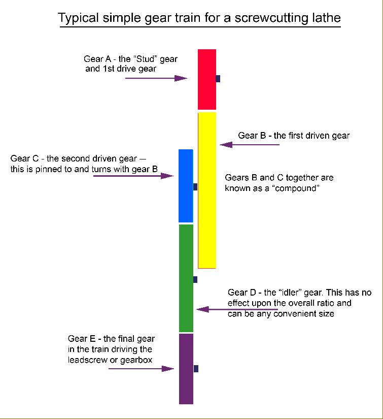
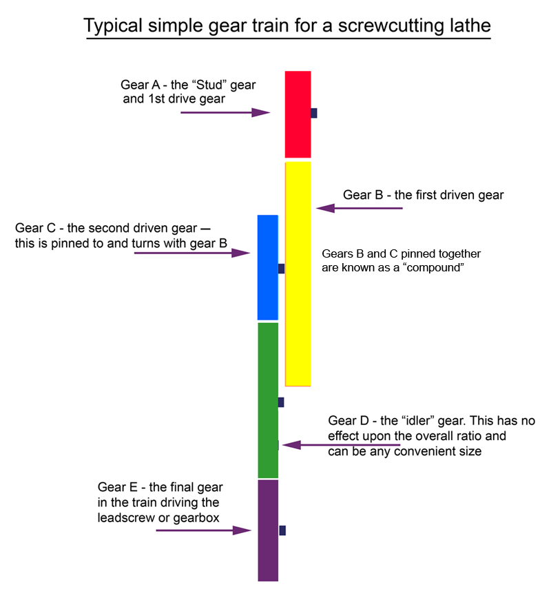
The results are displayed as a list of changewheels to use - and where they should be mounted described in terms of "Driver" and "Driven" gears. The position of the "Driver" and "Driven" gears can be determined by reference to the changewheel diagram below - which is also reproduced here: gear-train.bmp (you might want to print it out). More detailed instructions can be found further down the page - please read them
Another screwcutting calculator program - for changewheels only and ready to use - is here.

Don't just jump in and attempt to use the programs, to get the best results read and understand these notes first - and if your lathe has a screwcutting gearbox it's even more important to go though the explanations and examples steadily.
The programs have been written to help with the following situations:
1) If your screwcutting chart is absent - or to calculate a new one.
2) Should changewheels be missing the programs will attempt to calculate alternative arrangements using the gears to hand
3) To generate a pitch not on a threading chart 
4) To calculate the missing changewheels necessary to make a more useful set
5) To generate metric pitches on an English lathe without using a 127 tooth gear

A book with screwcutting information most suitable for the amateur (and ideal to refresh the memory of the professional) is: "The Amateurs Lathe". This gives a complete breakdown of the process with simple-to-follow instructions that will enable even the complete beginner to cut threads successfully. Other useful publications include the inexpensive: "Screwcutting in the Lathe" and a newer, beautifully produced hard-back book that is highly recommended: "Screwcutting"

Remind me which program to use…..
NthreadsP is the program for lathes with screwcutting by changewheels. BoxftrhreadP is for lathes with a quick-change gearbox. Note: some lathes with changewheels for screwcutting have, rather handily,  a two or three speed box that gives two or three sets of ratios for each train of gears. Examples include some Models of the Harrison L5 and certain early American Sheldon lathes

Background:
Calculations show that a set of 20 gears will generate, for example, 380 sets of 2-gear arrangements, 29,070 sets of 4-gear and 775,200 sets of 6-gear: a total of 804,650. By calculating all these possibilities it is possible to set up gear trains that will generate pitches with only a very minor or even zero pitch errors. It would, of course, be extremely laborious to calculate all these many arrangements by trial-and-error method with a pocket calculator - but a computer program can do it very quickly.

The Gear Train:
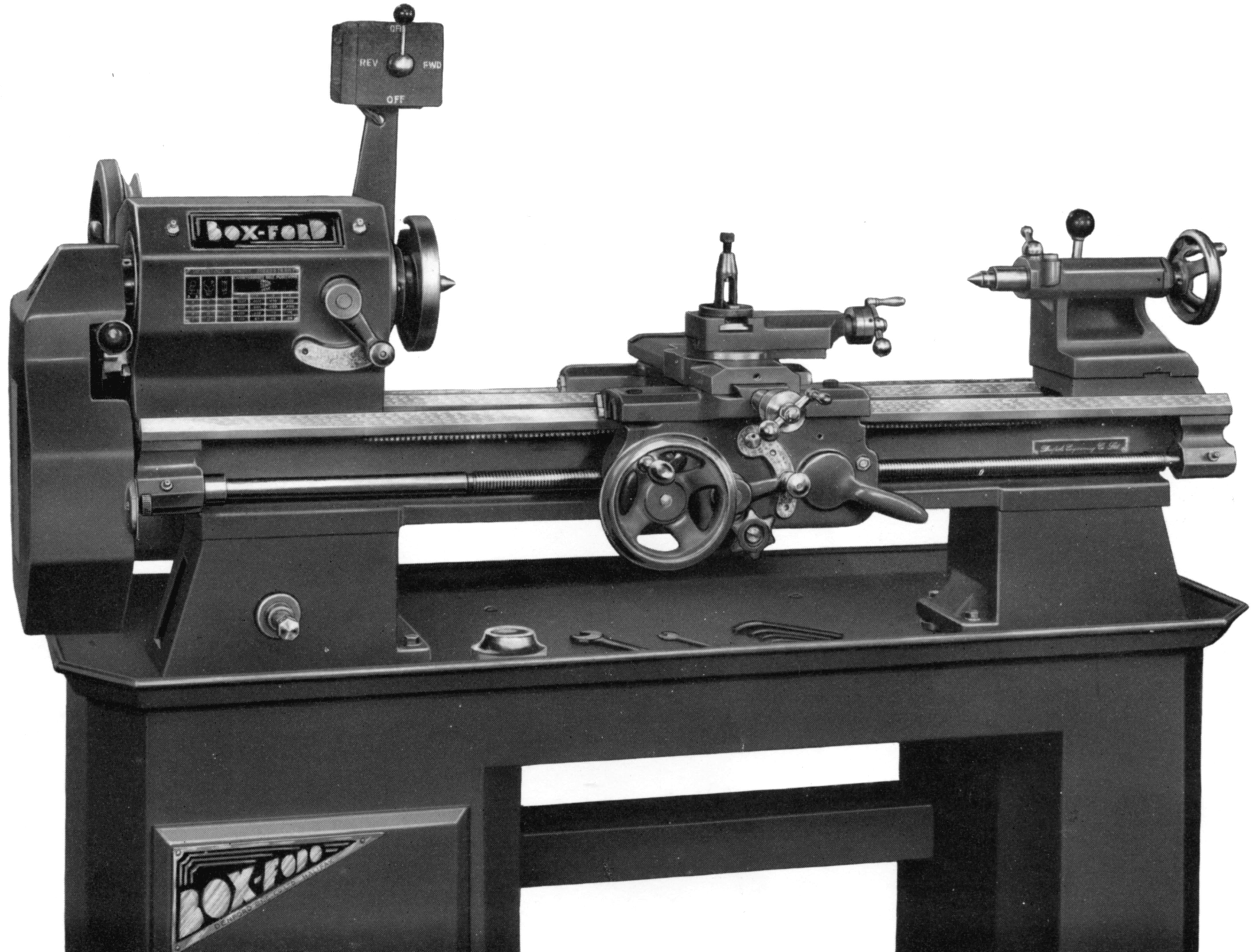
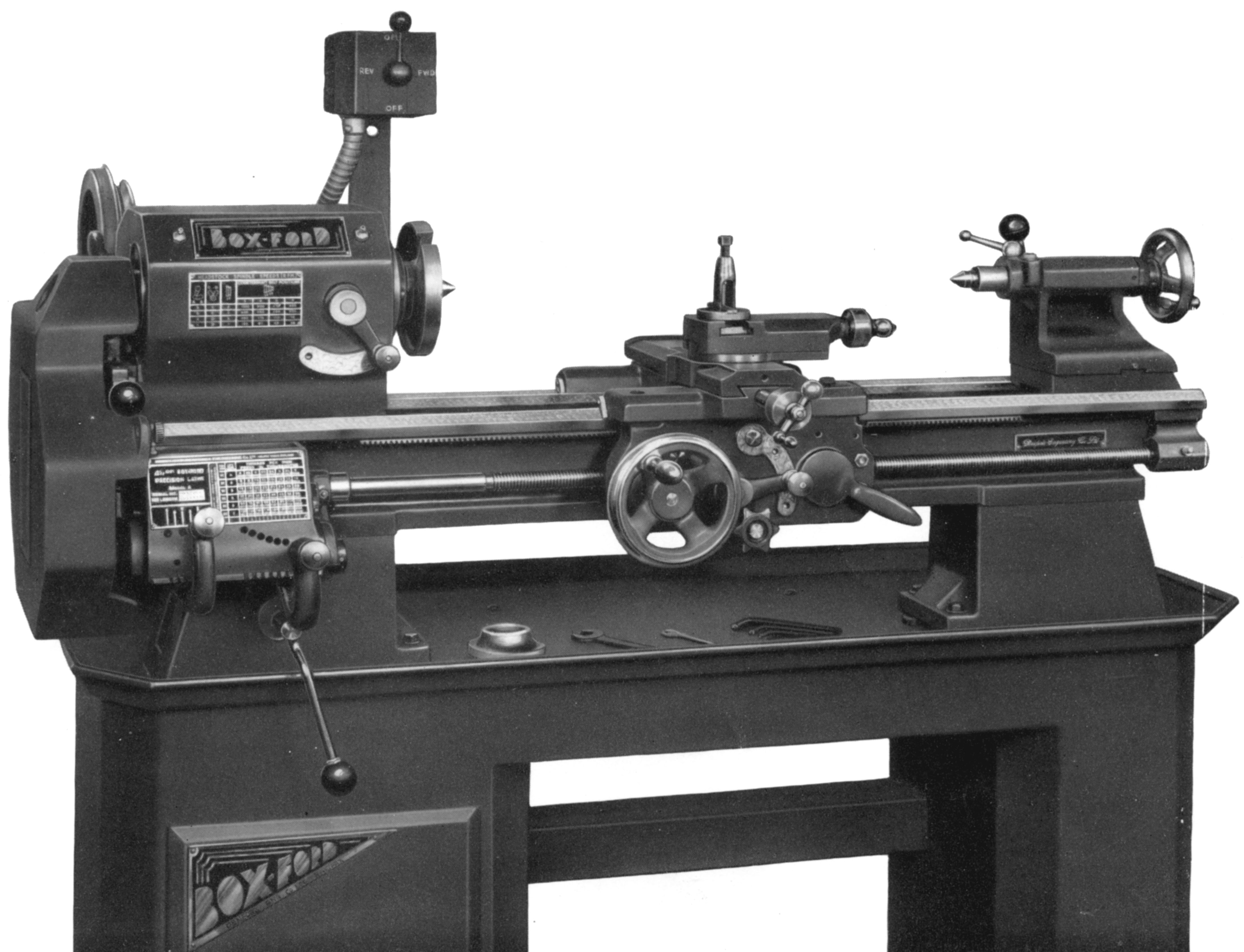
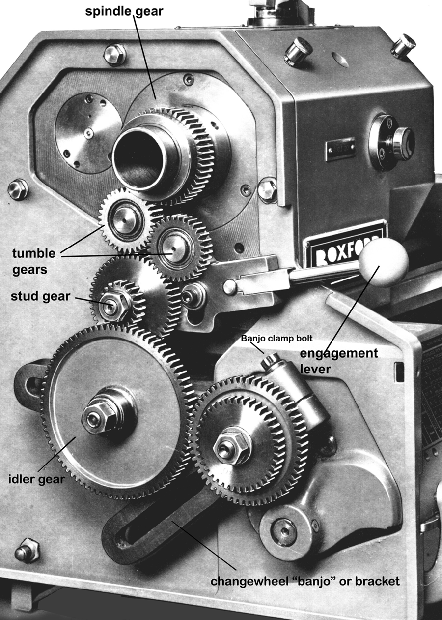
Typical lathes for which the NthreadsP program was written include the smaller British and American types such as Myford, South Bend, Boxford, Colchester, Drummond, Atlas, Craftsman, Sheldon, Delta, Rockwell, etc.  For lathes that have either screwcutting by changewheels or a screwcutting gearbox a diagram of a typical set-up is shown below with the gears coloured - and in gear-train.bmp - together with a photograph of a similar arrangement here: changewheels.bmp. Briefly, a gear on the end of the main headstock spindle engages with a "tumble-reverse mechanism" - two gears on a pivoting arm arranged to reverse the drive. The tumble-reverse mechanism has an output gear (often referred to as the "Stud" gear) driving a train of gears, this being, sometimes, a "
compound set" where one or more studs carry two gears that rotate together as they fastened to each other  by a key or pin. An important point is that the stud gear is usually made removable, allowing it to be part of the screwcutting train while also providing a quick and easy means of slowing down or speeding up the minimum carriage feed rate..
To space the gear-train out and make it physically possible to build, idler gears are also sometimes included, but these, no matter how large, or small - or how many - have no effect upon the overall ratio.
The "Stud" gear "A" on the end of the primary shaft (shown red on gear-train.bmp) is the first DRIVER gear. It turns a gear "B" on the 1st stud (shown in yellow) this being a DRIVEN gear.
The adjacent gear "C" (coloured blue on the 1st. Stud)  is a DRIVER gear and is fastened to and turns with gear B - the arrangement being known as "compound". Gear C, in turn, drives either an idler gear (in green) or direct to the gear (in purple) fitted on the end of the leadscrew or screwcutting gearbox input shaft.
In many cases spacing collars are needed to get the gear train in line - these can be plain distance pieces or often just spare gears.
The number of teeth on the idler gear (green) has no effect on the thread produced.
NB : Depending on the gears required to cut a given thread, it will sometimes be necessary to fit the idler gear on the first stud and a compound set of gear (two gears pinned together on one shaft) on the second.

"Simple" Gear-trains:
Frequently the train of changewheels can be simplified to just three gears: a driver (red gear on primary shaft), an idler (green gear) and the final driven gear (purple) on the leadscrew). Very occasionally the drive can be direct from output stud to leadscrew, or gearbox, with no idler gear in the train.
A note: 'Change
wheels' you say. Why not 'changegears'?  - the explanation is that, while laymen call gears "cogs", the rest of us use the term "gears" - but in the past a time-served, hands-on engineer would have referred to them as "wheels" - hence the "changewheels" (gears) you change to set up a particular screwcutting train. Watch and clockmakers also use the term "wheels" in place of "gears".
Continued below:


Continued:
How to use the programs:

Examine your lathe and see if it has a gear-train setup similar to that shown above (and in the gear-train.bmp file). If it not, the program may be unsuitable.
Check that one turn of the headstock spindle = one turn of the primary shaft and its "stud" gear: if not, see "Kludge Factor" below.
You may have a quick change gearbox/pre-select gearbox that allows you to run the BoxftrhreadP program instead of NthreadsP. See point 2.0
1.0   Run the program by double clicking on Nthreadp.exe (you should have un-zipped the
program already by using WinZIP) from
My Computer, Windows Explorer or use the run bar to open it. You can also create a short-cut icon to the program if you intend to use it frequently. In Windows 10 it seems to unzip without resorting to a third-party application.
1.1   Make a list of all the loose gears that you have to hand. The number of teeth on each is entered into the 24 boxes available. Enter 0 in the unused boxes if you have fewer than 24 gears.  Press "
save gearset" to save the gears for your lathe again.
It is only possible to save the gears for one model of lathe.
1.2   Find out what your leadscrew is by measuring it or looking up in your manual. It is critical that you correctly
identify whether the leadscrew is Metric or Imperial and what its exact pitch in mm or number of turns per inch (t.p.i) is. Enter this in the box for the leadscrew, check to see that you have ticked the first box if you have a metric leadscrew.
1.3   Decide what thread you would like to produce, tick the
inch-thread required or metric-thread required buttons accordingly and enter the pitch for metric/BA or the t.p.i. for BSP, UNC, UMF, BSW and BSF.
1.4   Enter a maximum error. This should be as low as possible; the best thread is the one with the minimum pitch error. Press the
Calculate button.

If you have too many results, gradually reduce the error until only the best results are shown. If you have no results, increase the allowable error and press calculate again.

If you can, choose a "simple" gear-train answer in preference to a "compound".
1.5   Once calculated you can write down the results or cut and paste by right clicking the results box. Left click "
select all", right click again, left click "copy" and paste to another application such as a word processor or spreadsheet.
1.6   To look for another thread go back to point 1.3. If you have finished, press the stop button.

Calculations NthreadsP for changewheel drive (gearbox instructions are lower down the page)
These are the calculations upon which the program is based--and also for assistance with some calculations required by the user:
FOR AN IMPERIAL (inch) LEADSCREW
TPI produced = DRIVEN/DRIVER  x  DRIVEN/DRIVER  x  LEADSCREW TPI
It does not matter in which order you place the driver or driven gears.
FOR A METRIC (mm) LEADSCREW
PITCH  produced = DRIVER/DRIVEN  x  DRIVER/DRIVEN  x  LEADSCREW PITCH
It does not matter in which order you place the driver or driven gears

EXAMPLE 1: (Imperial leadscrew, imperial thread required)
Leadscrew turns per inch :  8 (1/4 inch pitch)
No. of teeth on primary shaft gear (driver) : 50
No. of teeth on 1st stud driven gear: 80
No. of teeth on 1st stud driver gear: 32
No. of teeth on leadscrew gear (driven) : 60
TPI = 80/50 X 60/32 x 8 = 24
This will produce a 24-turns-per-inch thread

EXAMPLE 2:  (Imperial leadscrew, metric thread required)
Leadscrew Turns per inch :  8 (1/4 inch pitch)
No. of teeth on primary shaft gear: 48
No. of teeth on 1st stud driven gear: 50
No. of teeth on 1st stud driver gear: 36
No. of teeth on leadscrew gear (driven) : 44
TPI = 50/48 x 44/36 X 8 =     10.185 TPI
Convert to millimeters : Pitch in mm = 25.4 / TPI   
                                                               25.4 / 10.185 = 2.494 mm pitch
This equates to a 0.25% error against a 2.5-mm pitch.

EXAMPLE 3: (Metric leadscrew, metric thread required)
Leadscrew pitch: 2 mm (metric leadscrew)
No. of teeth on primary shaft gear: 80
No. of teeth on 1st stud driven gear: 80
No. of teeth on 1st stud driver gear: 36
No. of teeth on leadscrew gear (driven) : 48
PITCH = 80/80 x 36/48 x 2 = 1.5 mm                   

EXAMPLE 4: (Metric leadscrew, imperial thread required)
Leadscrew pitch: 2 mm (metric leadscrew)
No. of teeth on primary shaft gear: 32
No. of teeth on 1st stud driven gear: 36
No. of teeth on 1st stud driver gear: 25
No. of teeth on leadscrew gear (driven): 28

PITCH = 32/36 x 25/28 x 2 = 1.5873 mm       
Convert to TPI : TPI in mm = 25.4 / 1.5873 = 16.002 TPI
This equates to a 0.0125% error against a 1-mm pitch.         

EXAMPLE 5: (Imperial leadscrew, imperial thread required, "simple" gear-train solution)
Leadscrew Turns per inch:  8 (1/4 inch pitch)
No. of teeth on primary shaft gear (driver): 40
No. of teeth on 1st stud driven gear: idler
No. of teeth on 1st stud driver gear: idler
No. of teeth on leadscrew gear (driven): 80
TPI = 80/40 x  8 = 16
This will produce a 16-turns-per-inch thread using a "simple" geartain

2) Instructions for BoxftrhreadP are as follows:

Run the program as described in 1.0 by running BoxthreadP.exe . 
2.1   Proceed as point 1.1, then work out the gear ratios for the gearbox part of the lathe (see.
BoxftrhreadP calculations) and make a reference table for yourself to relate the lever positions to the ratio. Press "Edit quickbox" to enter these ratios. Start by entering the number of ratios to consider in the top box and then type a ratio into each box starting on the top lhs and working down. Press "
save current data" and "press to stop". Restart the program, press "edit quickbox" and check that all ratios are correctly typed and positioned in the white boxes. Check that all gears are correctly entered in the main window as per 1.1 above.
2.2   Proceed as point 1.2
2.3   Proceed as point 1.3
2.4   Proceed as in point 1.4. If you have many gear ratios the number of results will frequently be high; to save, copy and paste the results to another application as per point 1.5.
Depending on the speed of your computer, and how many ratios you have, BoxfthreadP may take a little while to do each computation and require some patience.
2.5   To look for another thread go back to point 2.3. if you have finished, press the stop button.

KLUDGE FACTOR:
Some lathes have their gear-train configured in a different way. In an attempt to make the program work with these a "Kludge Factor" is included where (for a variety of reasons) the primary shaft does not run at spindle speed. The Kludge Factor is, in essence, a factor that will be required on some lathes to obtain useful results. The BoxfthreadP version does not have the kludge factor facility but this can be multiplied into your gear ratios if using the BoxfthreadP version of the program.
     
KF =  Spindle speed/First driver speed (Change this to first driver/spindle in later version)
or: KF =  No of teeth on primary shaft gear/no of teeth on spindle gear (may not be true for all lathes)
or: KF =  Actual TPI produced/TPI calculated by NthreadsP with KF of 1
or: KF =  Pitch calculated by NthreadsP with KF of 1/Actual pitch produced
You can work out the Kludge Factor from any of the above formulae - and it should always be the same.   
On lathes with a two-speed primary gear drive use the BoxthreadP program with 2 ratios.

THE CALCULATIONS (BoxfthreadP):

If you have a gearbox in addition to a typical gear-train enter the number of ratios,
and the ratios which you will have to calculate, as follows.
Ratio = No. teeth on Driver gear/No. teeth on Driven gear x  No. teeth on Driver gear/No. teeth on Driven gear etc
or: Ratio = Speed of gearbox output shaft/Speed of gearbox input shaft
or: Ratio =  TPI calculated by NthreadsP/Actual TPI produced
0r: Ratio = actual pitch produced/pitch calculated by NthreadsP
To use the program results work backwards from the answer to find the lever positions
For most lathes the input gear to the quick-change gearbox is usually the "leadscrew gear" - but this will depend on the make and model of lathe.

FILENAMES
The following files relate to the 2 programs
NthreadP.doc   This document
NthreadP.exe  Application
nthreadp.txt  Save gear set file (used by NthreadP and BoxfthreadP)
Geartrain.bmp Drawing of typical geartrain
BoxfthreadP.exe Application
quickbox.txt  Save gear ratio set (used only by BoxfthreadP)..


Typical changewheel set-up as used by a South Bend 9-inch lathe

Typical screwcutting chart showing how to arrange the changewheels


Parts Home Page

Screwcutting    Countershafts    Backgear    The Watchmaker's Lathe   

Tumble Reverse   Quick-change Toolholders   Fitting a Chuck   

Spindle Nose Fittings    More Names of Parts   Epicyclic Backgears

Stuck Chuck   Countershafts, Jackshafts & Spindle Speeds   Oiling

   Reading Microscopes, Bevel Protractors, Combination Squares
and using Calipers & Dividers, etc.

Be sure to click the hyperlinks above for a complete picture
of how a lathe and associated equipment functions

lathes.co.uk
The "NthreadsP" and "BoxfthreadP" Programs
for Screwcutting Lathes

email: tony@lathes.co.uk
Home   Machine Tool Archive   Machine-tools for Sale & Wanted
Machine Tool Manuals   Machine Tool Catalogues   Belts   
Books   Accessories