|
Home Machine Tool Archive Machine-tools for Sale & Wanted Boxford Home Page Boxford Models A, B, C, AUD, BUD & CUD Model ME10 Boxford VSL & 500 Vari-Speed Model T & TUD Training Lathes Miniature Precision Boxfords Larger Precision Boxford Model CSB AUD Photo Essay Serial Numbers Screwcutting Gearbox Boxford Accessories Drive Systems Precision Tools South Bend Clones Late Model Boxfords Spare Parts For Sale Catalogue Covers Gap-bed Boxford Boxford Aprons Little Giant Tool Post Grinder We also supply changewheels and many other spares including We also supply changewheels and other spares including |
||


|
|
||
|
|
|
|
|
|

|
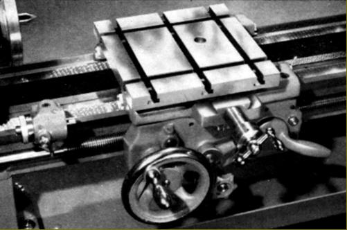
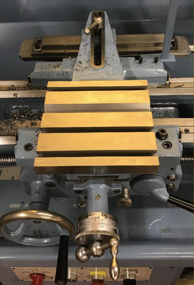
Boring TableT slotted cross slide and boring table. Some cross slides had only one T slot to the rear, others had three or even four. The boring table, always a comparatively expensive option, simply slid into position in place of the cross slide; today, it is a rare to find one with a used machine. New T-slotted slides are available, email for details. |
|
|
|
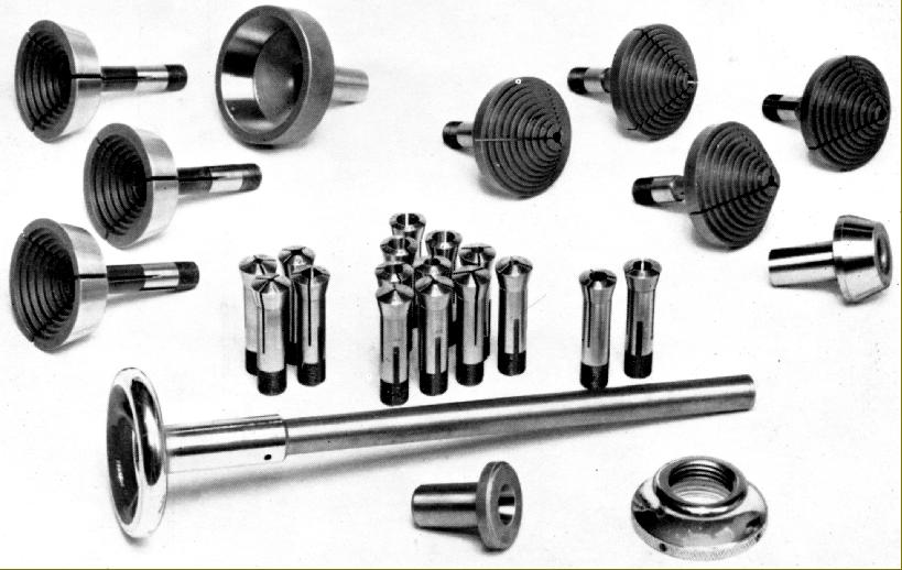
Draw-in collet attachment: Handwheel and hollow draw bar, tapered closing sleeve and spindle-nose thread protector. If you need to make one, here is the data: the draw tube is 3/4 inch OD and the bore at the collet end 19/32 (0.594) inch diameter. At the collet end it is tapped with a 26 t.p.i right-hand 60-degree (American) V thread, for a length of 3/4 inch. The maximum diameter of the (female) thread is 0.645 inch, i.e. the depth of thread is (0.645 - 0.594)/2 = 0.0256 inches. |
||
|
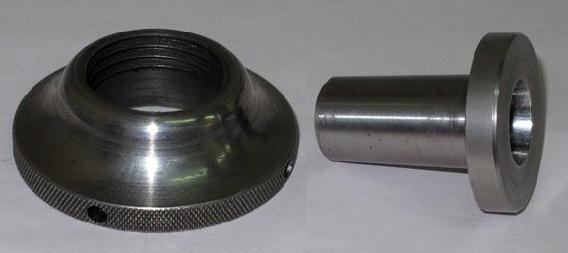
Collet nose adapter and protector as used on South Bend 9-inch lathes and early models of the Boxford. Later Boxford versions of the cap had a slightly different exterior profile and were chrome plated |
||
|
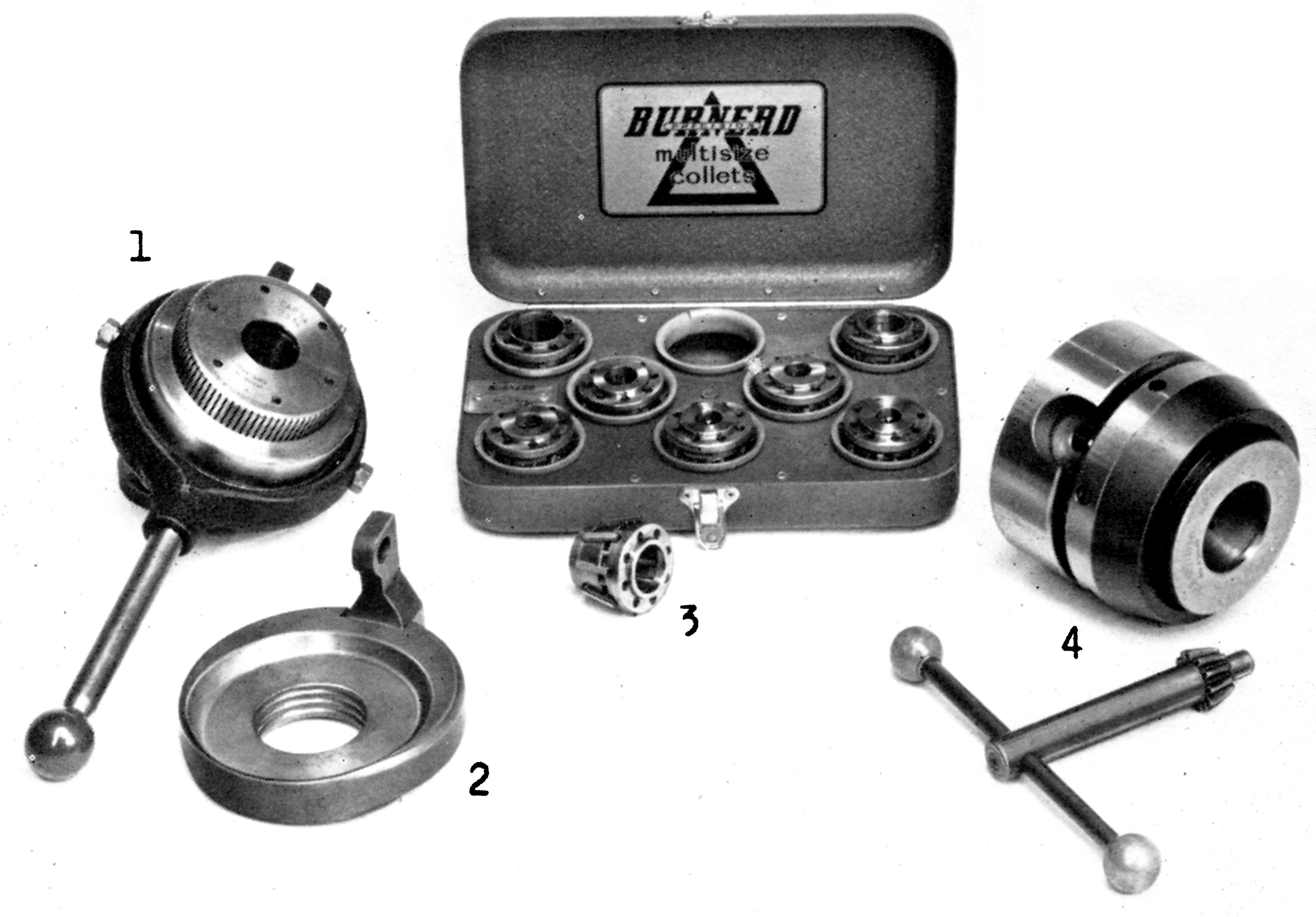
A wonderfully useful, if rare and originally expensive fitting, a Burnerd Multi-size collet chuck set. Two chucks were available, the No.1 was a lever-action type (that used Part No.2 as a backing plate to form the fulcrum point for the lever), and No. 4, a slower-to-use, key-operated type. Both chucks used "spring" collets (3) that could be adjusted over a small range of size (covering both inch and metric bar-stock metric) by screwing in or out a ring on the chuck's face |
||
|
|
||
|
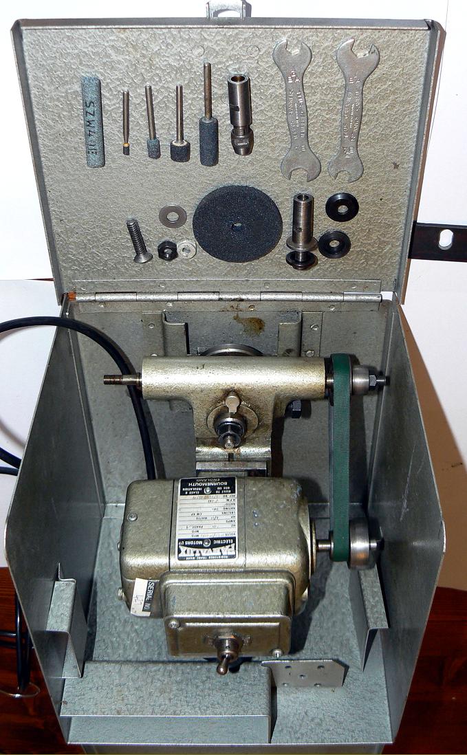
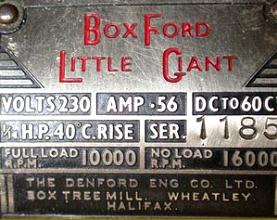
A late-model example of the expensive-when-new "Little Giant" toolpost grinder> |

|
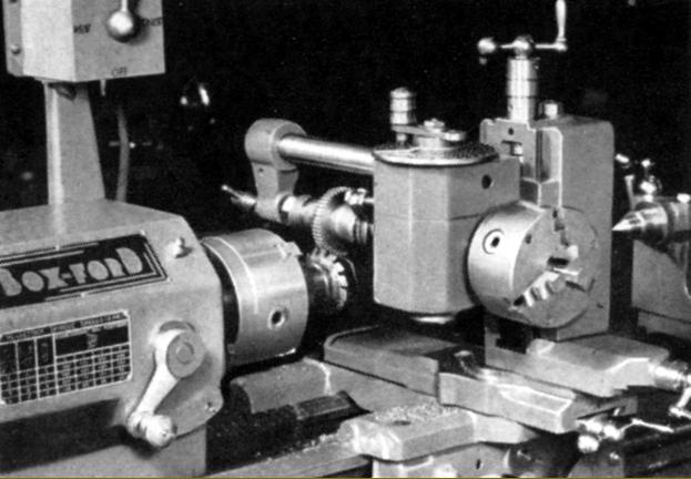
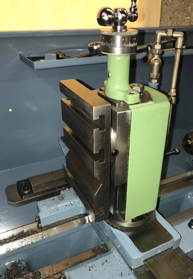
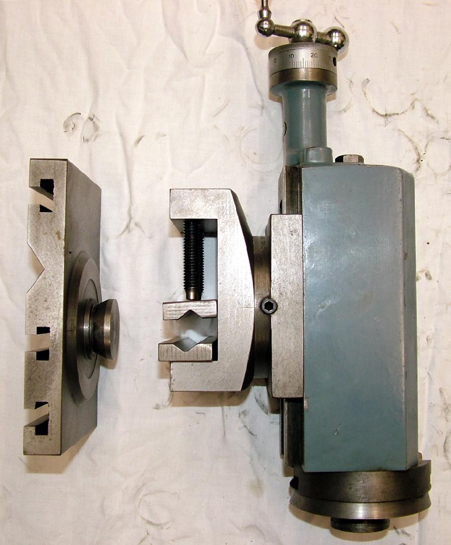
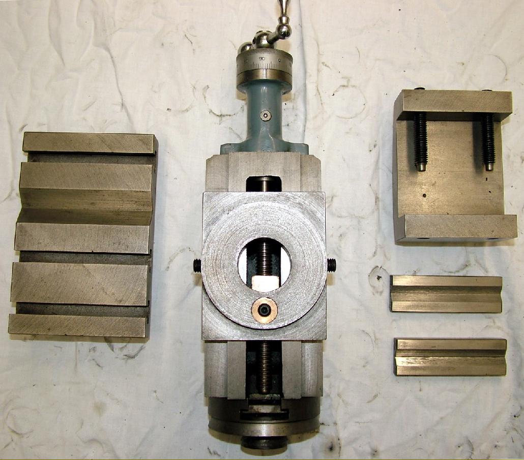
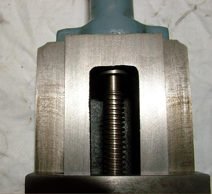
Boxford milling and dividing attachment. This cleverly designed, beautifully made but very expensive (and difficult-to-find) assembly features completely interchangeable components. The T slotted table, vice and dividing unit all have a mounting spigot identical to that used on the top slide - and so can be fitted either to the milling column, or used independently on the cross slide. |
||
|
|
|
|
|
Boxford milling and dividing attachment. This cleverly designed, beautifully made but very expensive (and difficult-to-find) assembly featured completely interchangeable components. The T slotted table, vice and dividing unit all had a mounting spigot identical to that used on the top slide - and so could be fitted to either the milling column, or used independently on the cross slide. |

Produced in very limited
numbers - the ultra-rare and very useful "compound" milling slide
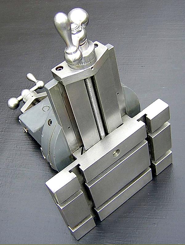
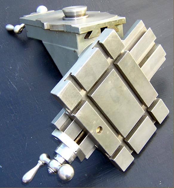
|
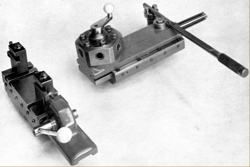
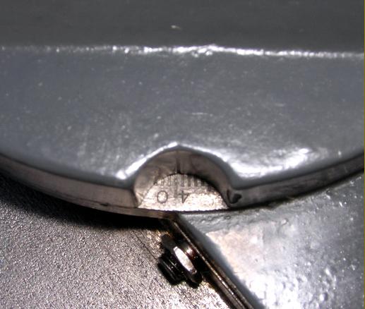
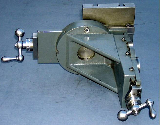
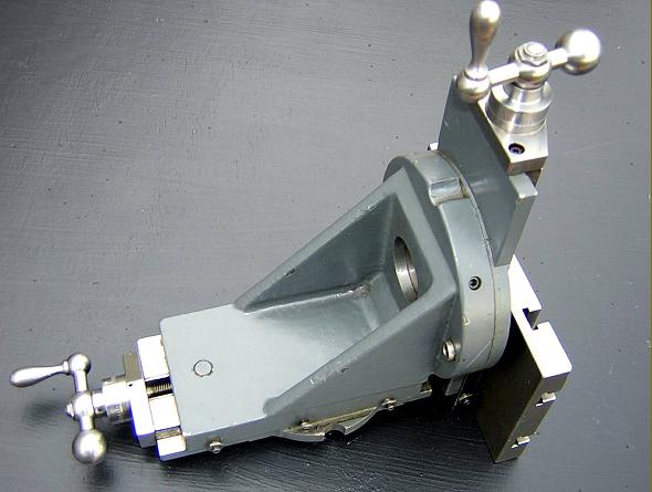
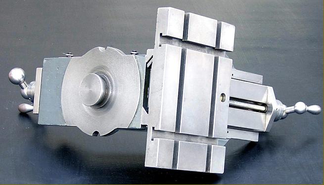
Very hard to find - though very useful to own - the Boxford Compound milling slide mounted in place of the top slide. With 360° of swivel on the base and something like 270° on the T-slotted slide before it contacted the bed, it was possible to arrange even awkward jobs satisfactorily. |
|
Home Machine Tool Archive Machine-tools for Sale & Wanted Boxford Home Page Boxford Models A, B, C, AUD, BUD & CUD Model ME10 Boxford VSL & 500 Vari-Speed Model T & TUD Training Lathes Miniature Precision Boxfords Larger Precision Boxford Model CSB AUD Photo Essay Serial Numbers Screwcutting Gearbox Boxford Accessories Drive Systems Precision Tools South Bend Clones Late Model Boxfords Spare Parts For Sale Catalogue Covers Gap-bed Boxford Boxford Aprons Little Giant Tool Post Grinder We also supply changewheels and many other spares including We also supply changewheels and other spares including |
||