|
Home Machine Tool Archive Machine-tools for Sale & Wanted Models A, B, C, & AUD, BUD & CUD in Mk. 1 and Mk. 2 Versions Boxford Home Page Boxford Models A, B, C, AUD, BUD & CUD Model ME10 Boxford VSL & 500 Vari-Speed Model T & TUD Training Lathes Miniature Precision Boxfords Larger Precision Boxford Model CSB AUD Photo Essay Serial Numbers Screwcutting Gearbox Boxford Accessories Drive Systems Precision Tools South Bend Clones Late Model Boxfords Spare Parts For Sale Catalogue Covers Gap-bed Boxford Boxford Aprons Little Giant Tool Post Grinder A detailed Manual & Parts List is available for all Boxford lathes We also supply changewheels and many other spares including |
|
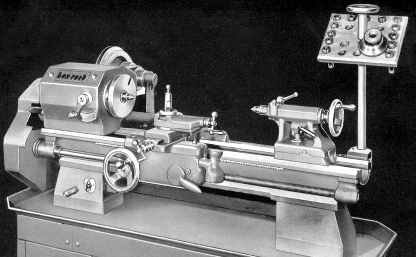
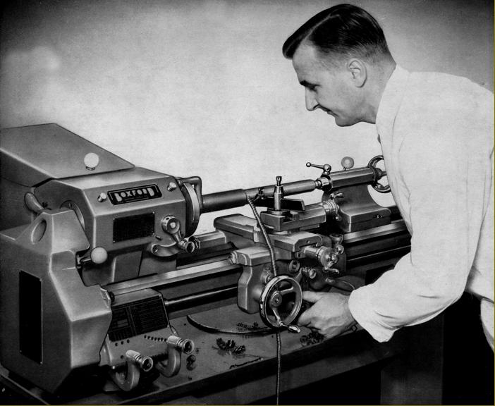
Above: the earliest known publicity photograph of a Boxford, this 1948 Model C had 3-step flat belt drive to the headstock, no headstock or countershaft belt-run guards, a tailstock held to the bed by a simple vertical bolt through the clamp plate and the electrical switch on the headstock-end bed foot. The countershaft was of the integral type, fastened to the back of the lathe and mounted on slider rails with a push/pull quick-action "screw" - the hexagon head of which can be seen protruding through the front of the bed foot. The collet tray clamped to the bed at the headstock end held not only the collets but the draw tube, spindle insert adaptor and thread protector. |
|
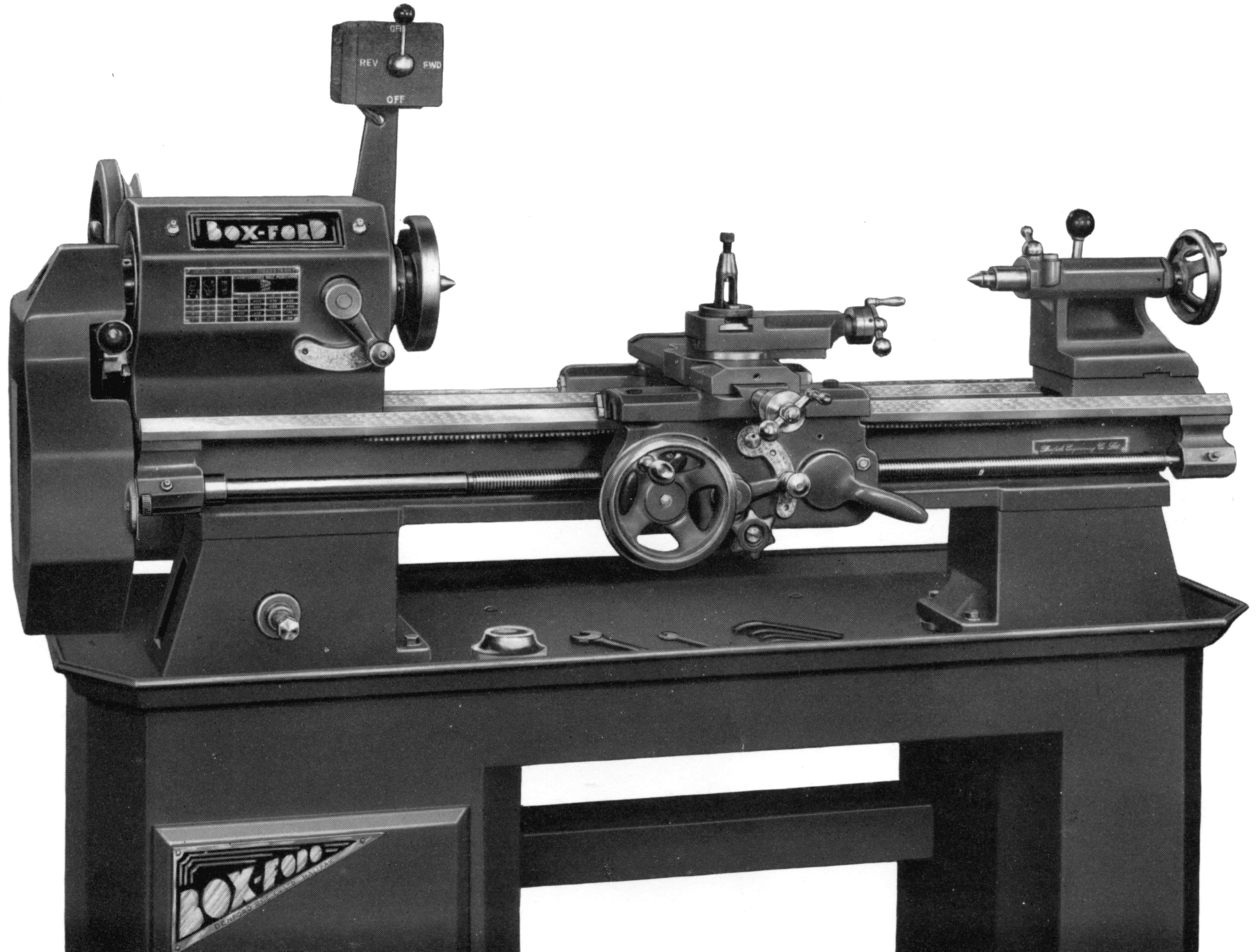
Circa 1952/3 Model A with screwcutting gearbox and power cross feed. The early form of quick-lock countershaft with its front-mounted handle was still in use and the belt run from the countershaft remained unguarded. |
|
|
|
|
|
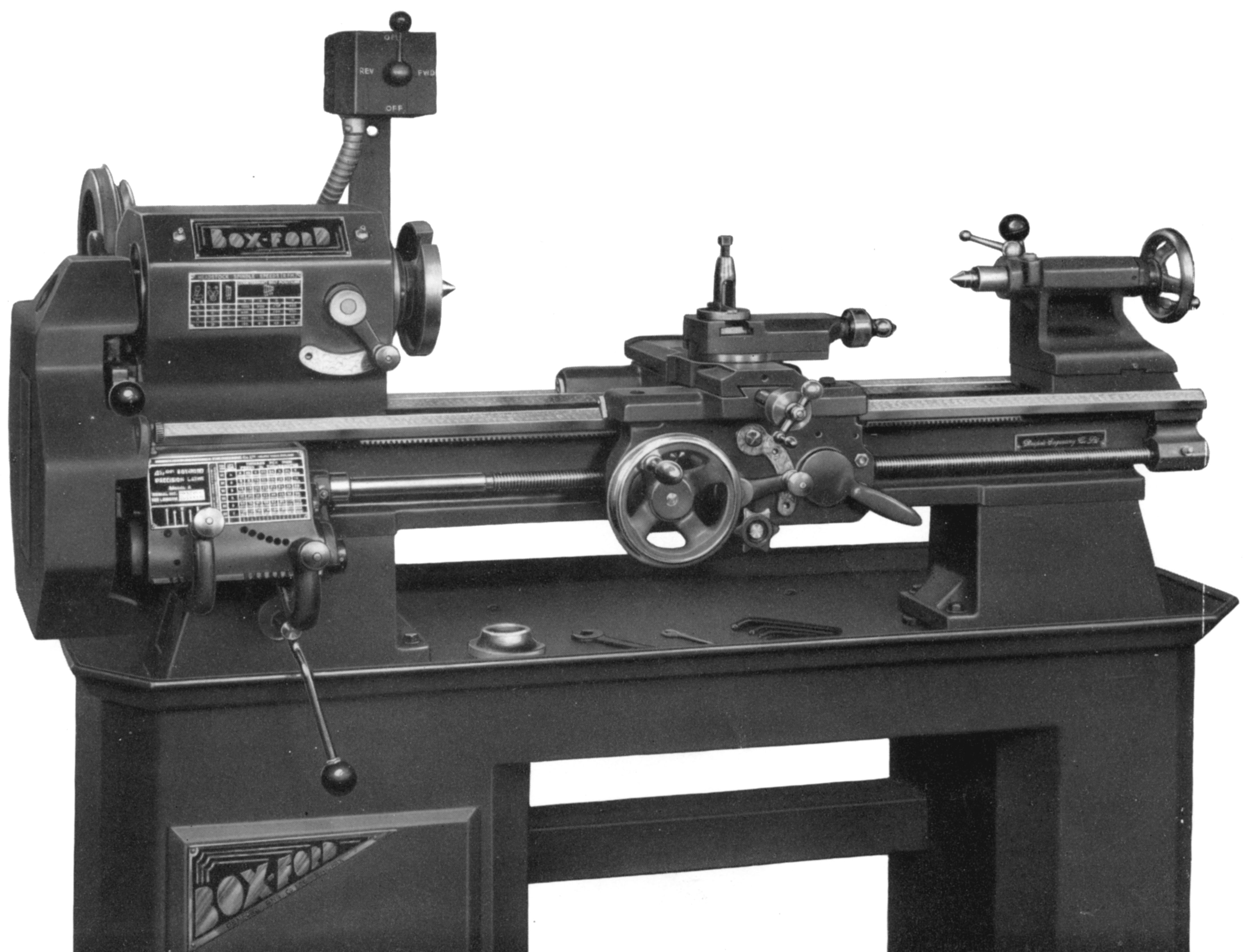
Later Boxford Model A with screwcutting gearbox and power cross feed. By the early 1950s the belt runs were completely guarded, the tailstock had a captive locking handle working though a cam and the electrical switch had been moved from the bed foot to a more convenient and safer position on a bracket bolted to the headstock. |
||
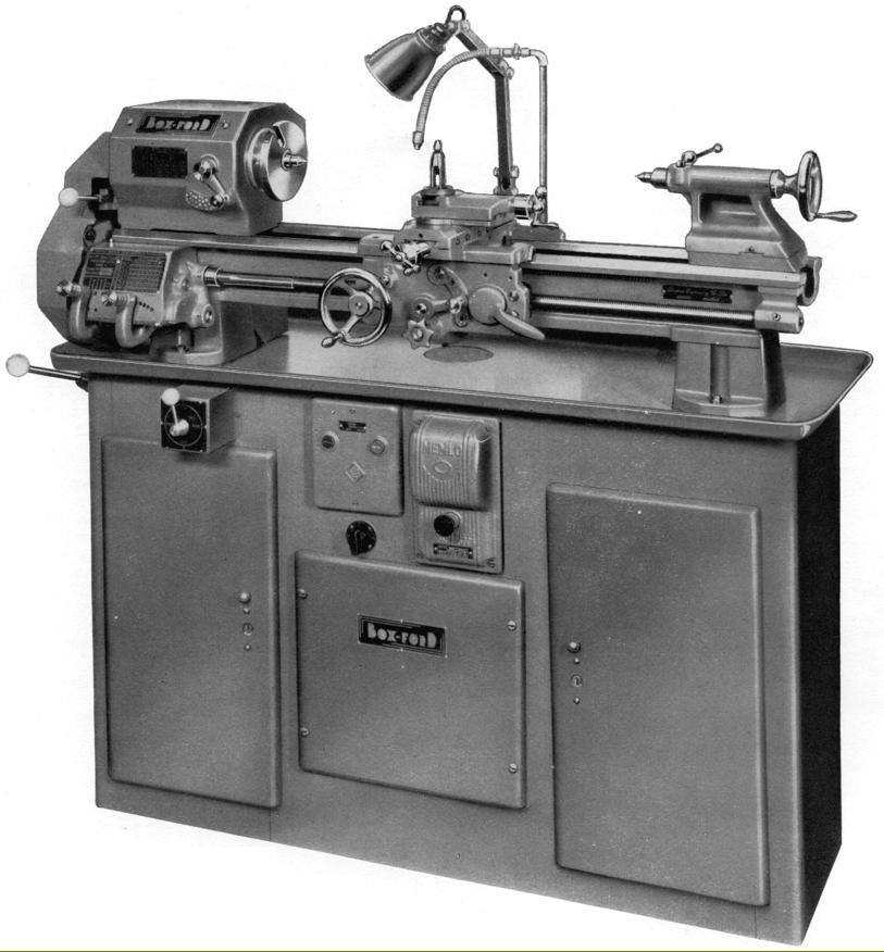
First version of the Underdrive lathe - in this case a Mk. 1 Model AUD with screwcutting gearbox and power sliding and surfacing feeds (note the countershaft belt-tensioning lever protruding through the left-hand face of the stand).
While rear-drive lathes had 6, 8 or 16 spindle speeds all the under-drive machines, with the exception of the variable-speed VSL, were limited to 10. With some variations, because of special orders or educational and training use, the usual range on the back-drive type was 30 to 1250 rpm whilst the Mk. 1 and Mk. 2 Underdrive types of all models (CUD, BUD and AUD) generally ran at 40, 66, 105, 165 and 270 r.p.m. in backgear and 210, 340, 540, 850 and 1400 r.p.m in open belt drive. However, on the latter machines (at extra cost) the factory could provide a more powerful motor and a "high-speed" pulley set that increased the maximum to just over 2000 r.p.m. - but at the sacrifice of increasing the bottom speed to such an extent that it was difficult for beginners to cut threads.
|
|
|
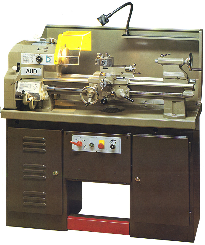
Some confusion surrounds exactly when the final version of the Underdrive, the Mk. 3, was put on the market. The official release date was May 1976, but machines have been found that pre-date this, for example: AUD III-33777 with a bed casting dated 1974 and with year also correctly corresponding to the Serial Number list. These lathes were distinguished by a more modern-looking stand complete with a neat splash-back, standard-fit low-voltage halogen light unit and a rather elegant grey and brown finish. However, the designation Mk. 3 was never acknowledged in the advertising literature, though it was used in the spares department to identify the particular models. During October and November 1981 the colour scheme was changed, temporarily, to green - a shade that can be replicated by ordering "Reseda Green B.S. Standard RAL6011". |
|
Mk. 2 headstock with a single lever to engage and disengage backgear. For safety the lever could be locked down into its two positions with Allen screws - and was also connected to a micro-switch that cut power if the handle was moved while the spindle was turning. Moving the lever slides the lathe "Bull Wheel" along the spindle to either engage or disengage it with the 4-step V-pulley while simultaneously moving the other gears into and out of mesh (to understand how backgear systems work see the article Lathe Backgear). |
||
|
Virtually unchanged since it's introduction in the early 1930s on the South Bend 9-inch, the power-feed apron has proved capable of a long, trouble-free life |
|
Another reliable component unaltered from first to last the screwcutting gearbox proved reliable - despite a lack of hardened gears and a reliance upon the operator applying an oil can occasionally as there was no oil-bath lubrication. |
Models A and AUD Screwcutting gearbox. This version produced inch-pitch threads; the metric gearbox had the position of the tumbler locating holes reversed left to right.
Models A, AUD, B and BUD Power cross feed apron . Besides power cross feed this apron provided a finer range of longitudinal feeds than the Model C all-changewheel model - the reduction through the apron's gear train meaning that the feed rate slowed by a factor of 0.3.
Boxford Mk 2 (5" centre height) compound slide rest assembly.
Later Boxfords had the top slide travel extended by 3/8" with the swivelling graduations inscribed on a plastic ring inserted into the cross slide. Although fitted as standard on these lathes the useful Dickson quick-set tool holder could be deleted and a cheaper "American" or clog-heel toolpost chosen instead.
|
Models A, B, C, & AUD, BUD & CUD in Mk. 1 and Mk. 2 Versions Boxford Home Page Boxford Models A, B, C, AUD, BUD & CUD Model ME10 Boxford VSL & 500 Vari-Speed Model T & TUD Training Lathes Miniature Precision Boxfords Larger Precision Boxford Model CSB AUD Photo Essay Serial Numbers Screwcutting Gearbox Drive Systems Precision Tools South Bend Clones Spare Parts For Sale Catalogue Covers Gap-bed Boxford Boxford Aprons We also supply changewheels and other spares including |
||