|
Home Machine Tool Archive Machine-tools Sale & Wanted a number of Parkson milling machines |
|
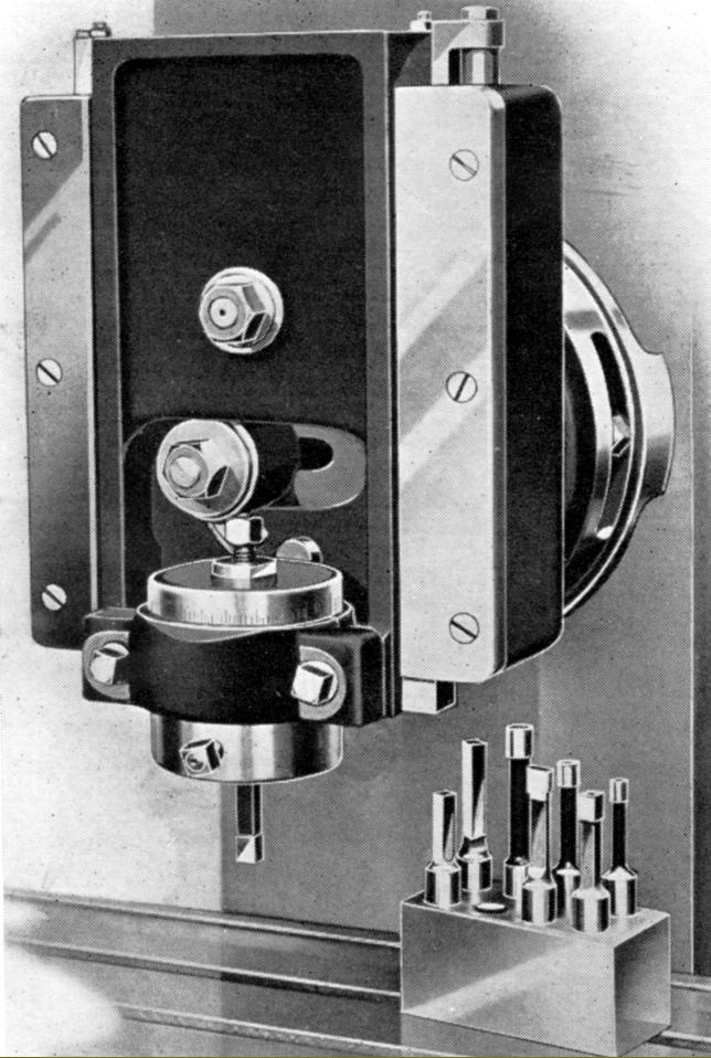
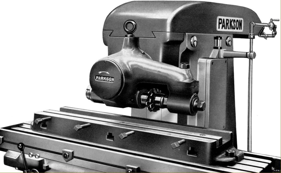
Slotting Head. The tool slide was driven from the miller's horizontal spindle by an adjustable crank pin that could be set to give a stroke between 0 and 3". The tool holder was arranged to take round-shank tools and could (unusually) be swivelled through 360 degrees - a micrometer collar being provided to read off the setting. |
|
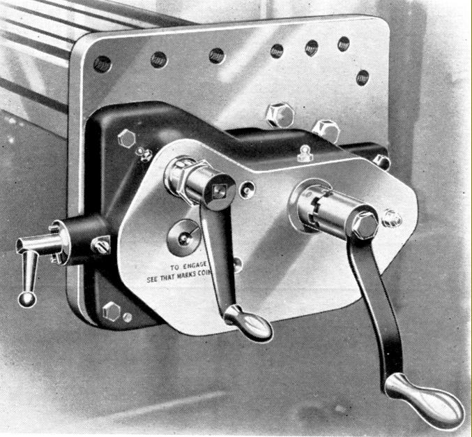
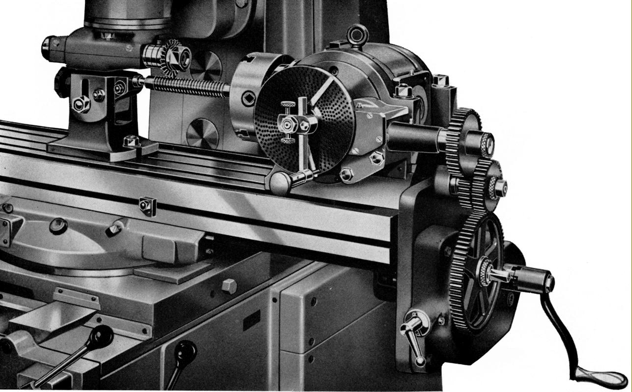
A useful device for special work was the Short Lead and Feed Reducer. Bolted to the end of table (shortening the travel by around 6 inches) the device contained gears with a 20 : 1 reduction that coupled to the table feed screw. The operator was thus able to move the table with great precision, if rather slowly. However, its main use was in conjunction with the power-driven dividing head (shown below), when it allowed screw threads or spirals of short single or multiple lead to be milled when the spindle had to make a complete revolution during a relatively short longitudinal movement of the table (so making the speed of cut far too high). By providing a very slow rate of table travel (the spindle, connected by changewheels to the feed screw still rotated at the same speed) it became possible to mill threads and spirals that would otherwise have been unobtainable - the intended range of leads being between 0.1 and 2 inches. |
|
|
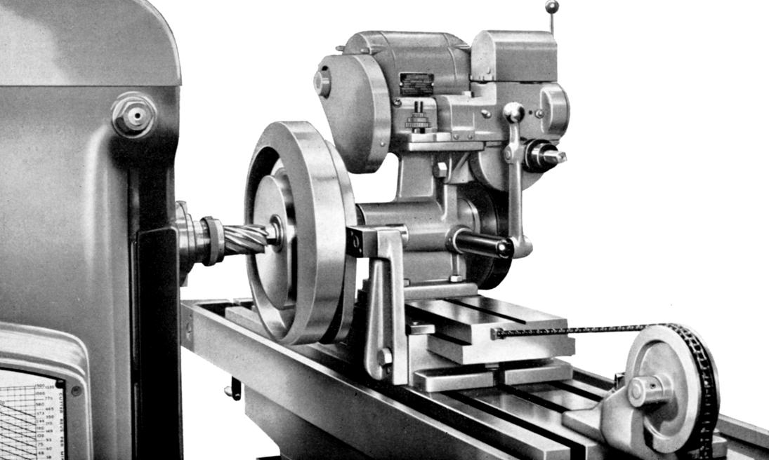
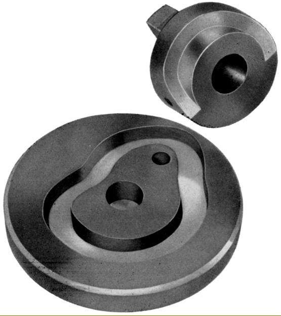
Cam Milling Attachment. Motor driven and intended for the production of face cams up to 16" in diameter and cylindrical cams up to 8" in diameter. Slots in the slide allowed the worm wheel spindle to be set right angles to the machine spindle and so a change made from cutting face to cylindrical work. The work was rotated by a 0.25 h.p. motor driving through spur and worm-and-wheel gearing. The large worm wheel was fixed to the spindle and ensured a steady rotation of the workpiece; a weight, attached to the slide by a chain removed backlash and kept the former plate in contact with a fixed runner. Three rates of feed were provided by pick-off gears (running on fixed centres) and either hand or power feed could be employed by engaging or disengaging a clutch.
|
|
|
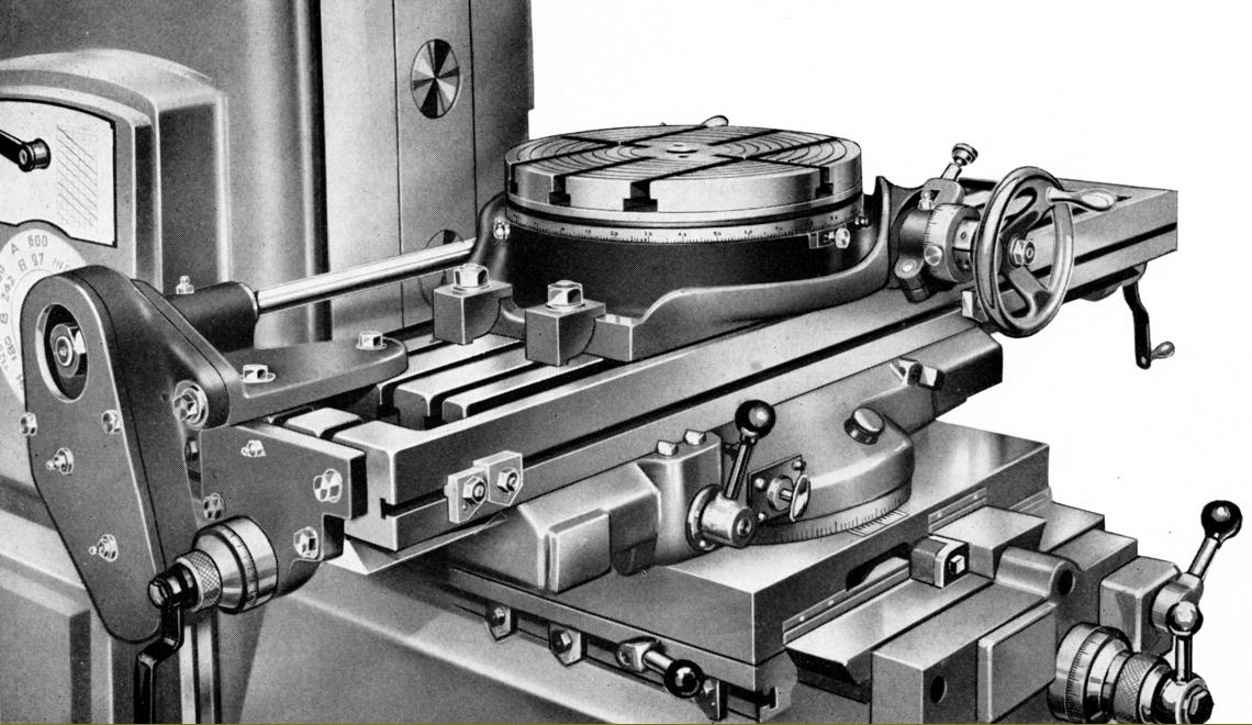
Rotary Table. Two sizes were available: 10" and 14" in diameter. The 10" was made for hand-feed only but the 1`4" could be coupled, as shown, with a power-feed shaft parallel to - but driven independently from - the table feed screw. Changes in the rate of rotation were made from the ordinary power-feed controls with a single lever for stop, start and reverse. It was possible to set up trips to disengage the feed and a free rotation of the table was possible by the usual means of disengaging the worm. |
|
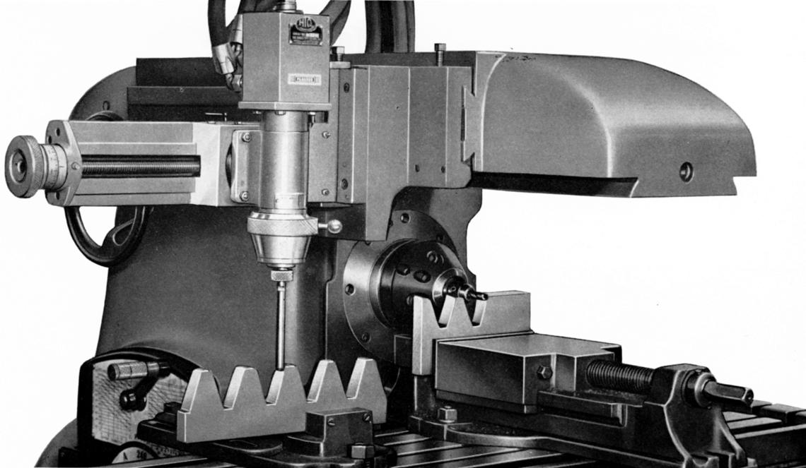
Rack Cutting Attachment . The assembly consisted of a cutter head, vice and the Indexing Device shown below. Cutters could be ganged up to a width of 3" on the 1.25" arbor with the outboard support allowing unusually heavy work to be tackled. |
|
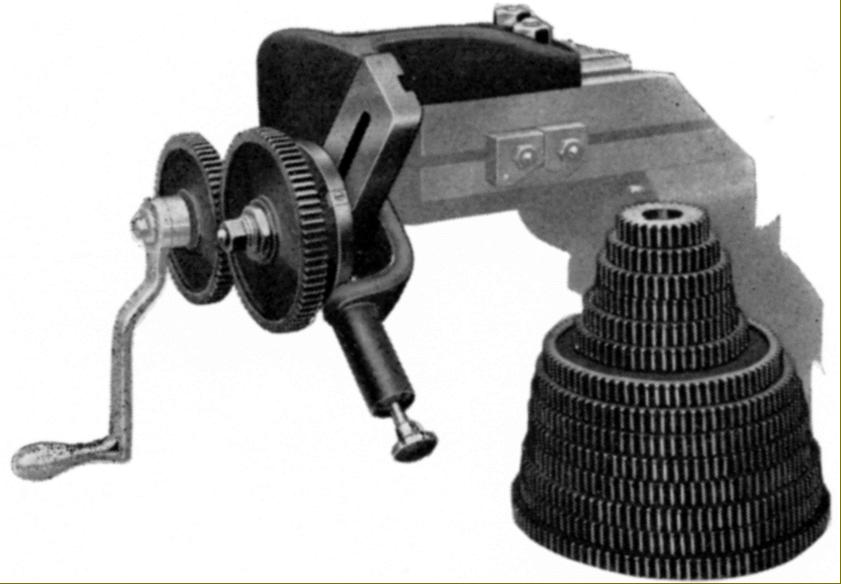
Indexing Device. Fitted to the end of the table and connected to the table feed screw, this unit consisted of an index plate with location plunger and sixteen changewheels. The divisions were obtained by a combination of the changewheels, the index plate making one-half turn or one complete turn. The plate was provided with two notches, one of which could be closed to prevent an incorrect selection |
|
Home Machine Tool Archive Machine-tools Sale & Wanted |
||