|
Paul Clausing started his machine-tool business in Lillian and Keota Streets in the town of Ottumwa, Iowa, USA in 1931 and was joined a year later by his brother, Otto. Their early products included a compound slide rest, manufactured for the Duro company together with various other lathe and machine tool accessories. A small wood-turning lathe was also offered, marketed by Sears,Roebuck, but sales, in a time of severe recession, were few and far between. However, by 1935, sufficient resources had been accumulated to begin the design of a metal turning lathe, and by 1937 the first extension to the original (and tiny) factory became necessary. A further extension was added in 1940 - which anticipated the vast increase in production that would be required by the war effort - and finally a completely new factory was erected in 1946, at 235 Richmond Street, on reclaimed land along the banks of the Des Moines River.
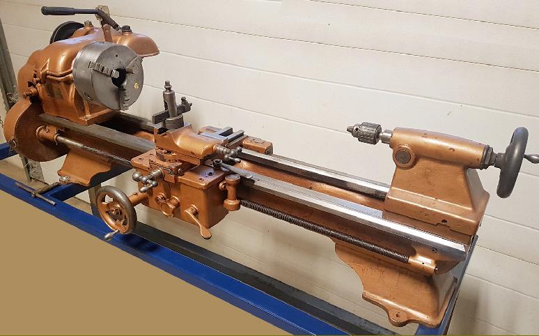
The company's range of 12 inch (6-inch centre height) V-bed lathes were built in two distinct Series, the 100 and 200; the earliest sales literature so far found for the 100 Series is marked "1938 Catalog" and so, presumably, was printed in 1937, production of the lathe having started in 1936 and with the first being shipped on June 8th of that year. The 200 Series was an entirely new design introduced very late in 1948, with the first delivery dispatched on March 31st., 1949. The original Series 100 lathe went through a series of rather rapid changes and was produced in three versions that we shall call - unofficially, and for identification purposes only - Mk. 1, Mk. 2 and Mk. 3.
In 1950 the Atlas Corporation purchased Clausing - and badged both the 100 and 200 Models with their name (there was no mention of Clausing) and changed the model numbers to 4800 and 6300 respectively. However, this caused some confusion with old customers, who demanded that their new lathes should be marked Clausing, and not Atlas. This entirely fair point was accepted by the Atlas who, after a few months, reverted (for a time) to the original name, reinstated the Type designations and applied a dual Atlas/Clausing badge. Unfortunately, the damage had been done and even today, as these older lathes are discovered and restored, those with an Atlas badge continue to puzzle new owners as to their origin. Finally, in 1969, the Atlas Company changed its name to Clausing Corp. to reflect the fact that the company wished to place greater emphasis on its involvement with larger, industrial-class machines.
Don Clausing, the son of Paul Clausing the company's founder, has recently made contact and written a fascinating account of the firm's growth and development from the early 1930s until 1950.
100 Series Mk. 1
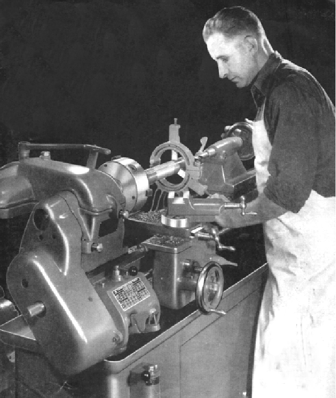
Obviously aimed at the amateur and light-duty professional repair-shop market the first Clausing 12-inch models had, in some respects, a rather "minimal" appearance; they were, however, well designed, with good attention to detail, and decently built - especially in the region of the headstock where, as standard, the 0.75" bore spindle was supported on Timken Taper roller bearings. A special high-speed model, the "Dual", intended to be used for both metal and wood turning, was fitted with a free-running, grease-sealed ball-bearing countershaft and offered with the option of a low-friction ball-bearing main spindle - the front being a double-row deep-groove type, the rear a single-row. The very first Clausing lathe was located after the war by Paul Clausing, and displayed in the entrance to their new factory, built in 1946.
With the availability of power cross feed and a proper screwcutting gearbox (on the Mk. 2 version) the specification of the new lathes quickly grew attractive enough gain the attention of professional workshops needing a compact but rugged machine - or one able to accommodate smaller jobs that would have tied up larger and more profitable lathes.
According to his son, Paul Clausing considered his main competitors in the 10-inch size category to be South Bend, Sheldon and, to some extent, Logan. However, the best-selling 10-inch lathe of the time was the mass-produced Atlas and the Clausing company took every opportunity to make this lathe appear less-well built than their own - although at the time, in the late 1930s, they were far too gentlemanly to actually mention competitors by name. The Clausing certainly had some advantages over the Atlas (which was also mass marketed under the Craftsman label by Sears, Roebuck) being made "entirely of iron and steel" and having "machine-cut gears" - both guarded references to the fact that many small parts on the Atlas, as well as all its gears, handwheels and pulleys were made from "Zamak", a mixture of aluminium, magnesium, copper and zinc that was pressure injected into hardened-steel dies and a material whose qualities was viewed with suspicion by many engineers The Clausing could also be had with a screwcutting gearbox, something not available for the Atlas until 1947 - though to be fair, a little difficulty with neighbors across the Pacific and Atlantic did obstruct development of all home-workshop machine tools for a few years.
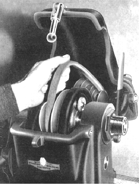
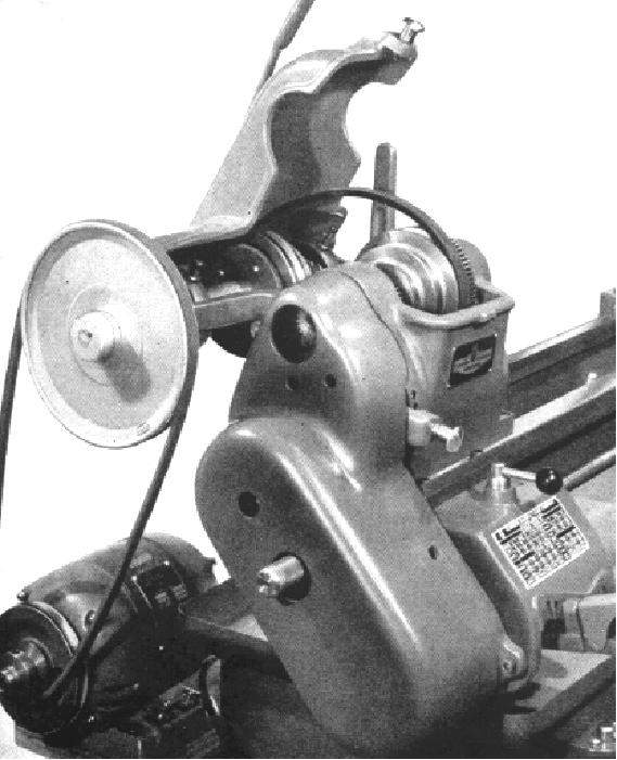
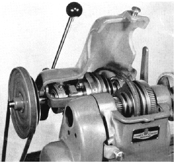
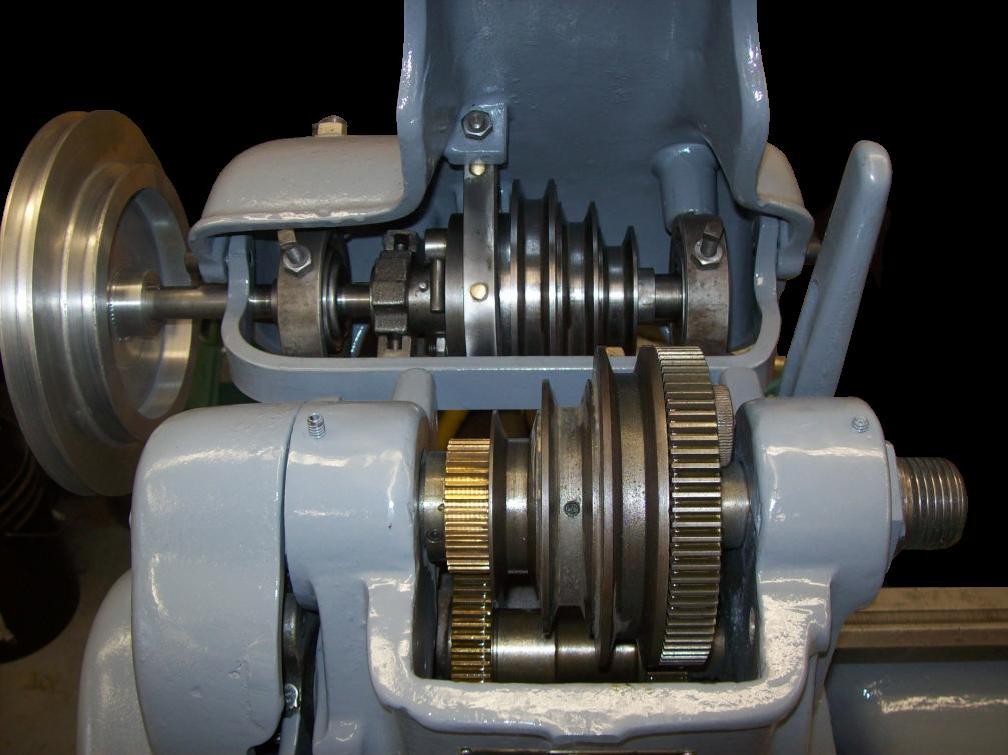
Supplied complete and almost ready to run, the Series 100 mounted a self-contained countershaft (with its bunting-graphite oil-less bearings carried in self-aligning hangers) fastened to the back of the headstock with the cast-iron headstock belt cover designed to be part of the assembly. The assembly was cleverly arranged so that, as the cover was lifted open to change speeds, the tension on the drive belt was relaxed. Unfortunately, the countershaft lacked an integral platform on which to mount the motor - that had to be bolted onto the bench directly underneath the countershaft and the belt tension arranged at a nominal setting. However, if the lathe was ordered on the maker's cast-iron legs (but not the other stands) an adjustable motor-support plate was provided. The basic lathe had three spindle speeds of 50, 73 and 134 rpm in backgear and 303, 437 and 801 in direct drive whilst the "Dual" - with its advertised ability to turn wood and plastic - had nine speeds of: 44, 73, and 115 in backgear and 260, 420, 680, 1225, 1960 and 3200 rpm in direct drive - achieved by using a two-step pulley drive from motor to countershaft. Three more speeds were, in practice, also available, but their use entailed engaging backgear on the higher-speed belt settings - an unwise and unnecessary thing to do.
Bolted to the bed at the front and secured with a clamp at the rear - in the manner of the South Bend Heavy Ten - the headstock was fitted with a substantial backgear assembly using 5/8" wide gears positioned directly underneath the headstock spindle. A rather pleasing safety feature was an inner cover that securely guarded the large "bull wheel" on the spindle when the main cover was opened. The compact mounting of the backgear was a deliberate attempt to engineer a headstock and countershaft assembly as short as possible from front to rear - without resorting to an ugly and unbalanced mass of pulleys mounted above the spindle line, or taking up an excessive amount of room front to back. For a 6-inch centre height lathe, capable of being bench mounted - and especially in comparison with a rear-drive 10-inch South Bend - it really was very compact and the drive system could, but for the bench-mounted motor, almost be considered an almost ideal design.
Designed into the compound slide rest assembly were some interesting compromises: to get the cutting tool up to the correct height, yet maximise the swing over the saddle and cross slide, the latter two were made relatively thin and, to compensate, the top slide deepened in section and constructed with a circular boss on its base that bolted to an identical boss on the cross slide. Unfortunately, the resulting assembly looked rather tall and inelegant and, to compensate (and also to counteract the increased leverage between the cutting tool and the cross slide ways) the cross slide was made a full nine inches long (to imagine this lever effect, try exaggerating the conditions and put the top slide on a three foot high post). The long cross slide, unlike the terribly short affairs found on so many other lathes (including the Atlas), also had the desirable effect of spreading wear from the slide's movements over nearly the full length of its ways - and so helped to prevent the formation of a hollow in the middle section of its travel. As ever, on lathes of this era, the micrometer dials were far too small but at least the dial markings were engraved, not rolled in.
It is interesting to compare the Clausing's "top-slide-on-a-post" arrangement to that of a "no-compromise" industrial lathe where, because it is assumed that it will be surrounded by many different sizes of lathes, all given jobs appropriate to their size and strength, the designer has no need to consider stretching its functionality to the limits. Instead, he can concentrate upon making it as rigid as possible by optimising the form of each component - and their relative sizes - to the best possible advantage within the design parameters and cost constraints he had been allocated. The Clausing, in comparison, would almost certainly have been the only lathe a private owner possessed and, making the most of its turning capacity in the way described above whilst sacrificing something in the way of ultimate rigidity, was a thoughtful decision by the manufacturer.
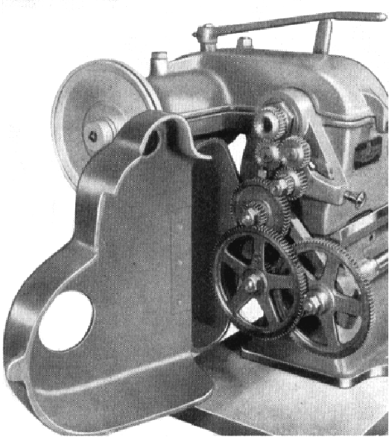
For screwcutting, a set of twelve hobbed-from-the-solid, half-inch wide, 16 pitch, 14.5 degree pressure-angle changewheels was provided - as well as the three gears (of which two were the largest available of 100 teeth each) fitted as standard to provide an ordinary feed to the carriage. Surprisingly, as delivered to the customer, these early lathes did not have the finest-possible feed set up - instead, the operator had to construct a compound set of changewheels from amongst those supplied.
Although the changewheels were guarded by a swing-open, cast-iron cover this, like the ones on contemporary South Bend lathes, had no form of retaining catch - whereas the ones produced by Atlas did. The gears of 32 teeth and below were made of steel, the larger ones of cast iron; they drove, via a tumble reverse mechanism, to a 3/4-inch diameter, Acme-form, 8 t.p.i leadscrew. The tumble-reverse selector lever was fitted with a spring-loaded, plunger-type engagement pin that faced the operator - a design, incidentally, that Clausing claimed to have invented, except that they didn't, it probably being first conceived by the British engineer Nasmyth in the early 1800s.
With a No. 2 Morse taper, 1-inch diameter barrel with 3 inches of travel (and ruler graduations every 1/16th of an inch) the tailstock was entirely functional. However, disappointingly, the main body was insubstantial and the barrel-locking clamp relied upon closing down a slot in the casting; fortunately, as a redeeming factor, it did have a useful, if rather awkward-to-operate, quick-action toggle clamp - positioned at the rear so that it would not tangle with the compound slide in close work.
Provided with two V-ways, one to guide the saddle, and one to align the tailstock, the bed on both Mk. 1 and Mk. 2 models was first rough milled and then stored for around a month for seasoning - a special shed being constructed (in 1946) for this purpose. A further session of machining then followed with the final fitting work and finish applied by hand with scrapers. On the Mk. 3 the hand scraping of the bed - and unfortunately the beautiful mottled finish this produced - was superseded by surface grinding, the move probably forced on the company by a shortage of men skilled enough to undertake the task; hand scraping, however, continued to be employed in fitting the saddle to the bed.
100 Series Mk. 2
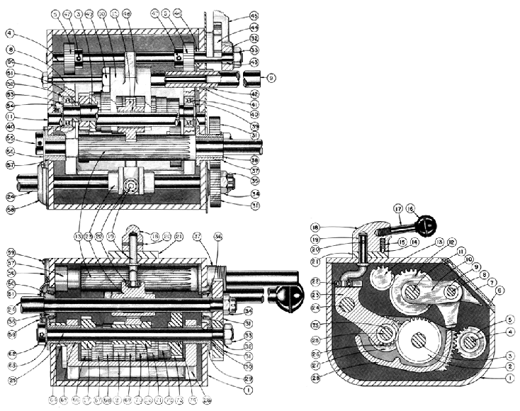
By 1940 several modifications, options and improvements had been introduced leading to what might be termed the "Mk. 2". The tailstock-end leadscrew hanger bearing was now held on with one rather than two bolts, the bed feet were lengthened, the shape of the end of the bed was changed and, more significantly, a screwcutting gearbox was offered for the first time. The box could generate 48 threads from 4 to 224 per inch and, unlike those fitted to some other similar-sized lathes, had the three independent controls of the traditional Norton quick-change design - a 3-position selector lever on top (marked A, B and C) a 2-position sliding gear under the changewheel cover (to select fine and screwcutting feeds) and an 8-position tumble lever on the front.
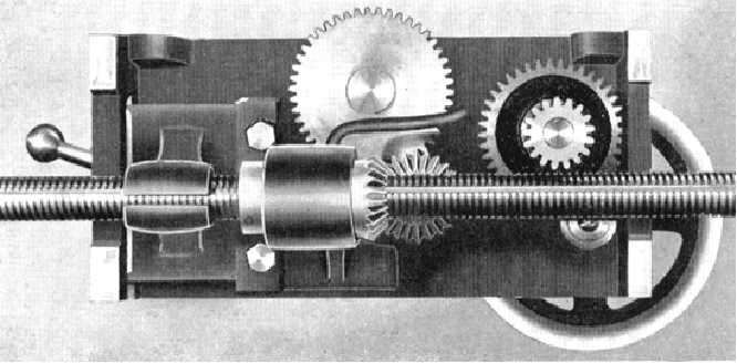
Initially fitted with a hand-powered cross feed only, the carriage was already offered with the option of a "Simple" power cross feed apron; however, unlike the system offered on competitors' lathes of a similar price, this did not provide a sliding feed - that could only be obtained by engaging - and wearing out - the leadscrew clasp nuts. With the introduction of a screwcutting gearbox a second more sophisticated "Automatic" apron (with a distinguishing 3-position selector lever on the front) became available; this much taller and deeper double-wall apron also drove the power sliding feed (the movement up and down the bed) leaving the leadscrew for screwcutting only. The improved apron (which was only available on lathes fitted with a screwcutting gearbox) was fitted with a simple but robust cone clutch, operated by turning a star-shaped knob on the front. The clutch protected the apron from damaging overloads but meant that (like many similar designs) there was no means of instantly disengaging the power feeds other than by unscrewing the knob - or unwisely trying to pull the selector lever into its neutral position whilst under load. The base of the apron, being enclosed, was used as an oil sump - the lubricant being splashed around the mechanism by the lower gears dipping into it.
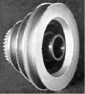
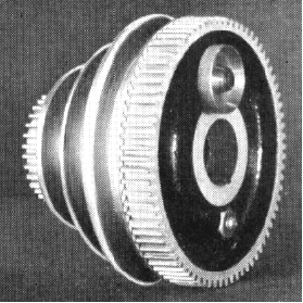
A combined cone-clutch and brake unit, built into the 3-step V pulley on the countershaft and with its operating-lever pivot on the right-hand side of the headstock cover, became an option on all but the "Dual" lathe - where it was fitted as standard. To operate the clutch the lever was moved to the right - whilst to bring the (external-band) brake into play - and arrest the rotational progress of the 56 lb lump of cast iron bolted to the faceplate - it was pushed further to the right.
A significant detail improvement concerned the mechanism for locking and unlocking the large spindle-mounted backgear bull wheel to the adjacent belt pulley. Previously, this had been the usual sort of spring-loaded pin, but was redesigned to produce a completely backlash-free connection, a most unusual state of affairs with any quick-release mechanism. The system was based on a split ring, fastened to the bull wheel, and machined to be a close but clear fit within a drum that was formed on the inside of the largest diameter of the cone pulley; the ring was expanded to grip the inside cone pulley - and positively locked - by a cam connected to a knurled thumb wheel.
100 Series Mk. 3
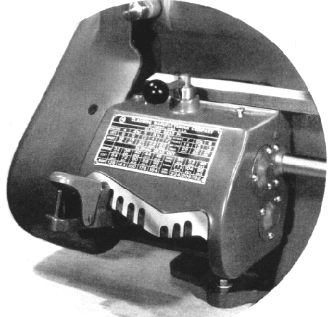
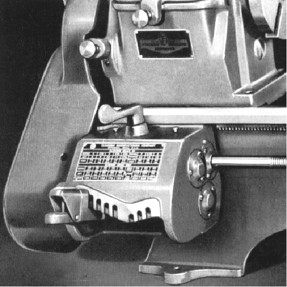
By 1944 the "Mk. 3" had made its appearance, its main identifying features being a completely new gearbox (with the gear-selector holes arranged in a distinctive "V" across the front, together with an usual and distinctive paddle-like design of engagement lever) - and a pin release for the headstock cover instead of a large toggle lever.
Mechanically the headstock was almost unchanged, the spindle having the same bore and No. 3 Morse taper - but the previous safety feature of a separate cover over the large backgear bull wheel (under the main belt cover) had, unfortunately, disappeared. As an option, the spindle could now be ordered with a hardened nose - ideal if production work involving many changes of fitting was envisaged.
Spindle speeds were slightly reduced, starting, on the ordinary model, at a more beginner-friendly 42 instead of 50 rpm and continuing through 73 and 120 rpm in backgear and 255, 437 and reaching 730 - instead of 801 rpm - in direct drive. An alternative range of speeds went from 50 through 73, 134, 250, 437 to 700 rpm.
Keeping its nine speeds, the "Dual" model continued in production but these, like those of the standard version, were all reduced by between 16 and 25 per cent with the top speed, unfortunately, falling from 3200 rpm to 2400 rpm - still fast, but hardly quick enough for its claimed wood-turning role.
Entirely new, the "V-front" gearbox was much more strongly built and used ball bearings throughout - however, it generated the same 48 pitches and feeds as before and used exactly the same (traditional Norton) method of selection.
To both give access to and simultaneously slacken the drive belt, the entire cast-iron top cover of the headstock still hinged upwards and backwards, but the retaining mechanism was changed from an over-centre toggle to a neat, spring-loaded, dome-headed pin.
Still produced in two versions, the apron was available in 'Simplified' or 'Automatic' forms. Whilst the former retained the single star-shaped knob that was screwed in to engage power-cross feed - and used the leadscrew thread to provide a sliding feed along the bed - the 'Automatic' apron was considerably modified with the 3-position selector lever replaced by a button. Neutral was in the middle whilst pushing the button in selected power sliding and pulling it out power surfacing. However, the drive was still through the same type of clutch as before - with no way of instantly disengaging the feed under power other than by wrestling with the selector button and hoping that, when it did come out of drive, the button did not overshoot its neutral position and select the other feed.
An interesting development of the Clausing 100 Series Mk. 3 lathe was sold through Metropolitan Distribution Ltd. of Truro, England under the name "Fortis" and "Fortis Imperial" and possibly, in addition, branded as the "Broadway" - though the latter is known to have carried standard Clausing badges as well and was probably just an ordinary import. The final incarnation of Metropolitan was a company called Luke Anthony Ltd. of Camborne, Cornwall, an organisation known to have survived into the early 1960s. In the late 1940s and early 1950s there was an acute shortage of machine tools on the UK market, with very long delivery times and, although the Forties looked, at a glance, exactly like the Clausing, they were not made in America. All the Fortis castings were subtly different and with a finish inferior to those by Clausing. In addition to other, smaller changes (detailed in the Fortis pages), a different screwcutting gearbox was used, one similar to the second version of the Clausing box, but without the "V" arrangement of the selector holes. The Fortis was advertised as being available in two versions, the "Standard" and "Precision", the latter "built to Schlesinger limits for toolroom or production work". In reality it is unlikely that the lathes were built to two different standards and the "precision" lathes would have been those that came through the post-build alignment tests with the 'highest scores'. Spindle speeds also differed from the Clausing being doubled in number to 12 and ranging from 40 to 2350 rpm. The stands were also unique with one incorporating a motor mount inside the left-hand cabinet leg.
Mk. 3a
Within four years the lathe was again modified, introducing changes that were to become a standard feature of the forthcoming, and quite different, 200 Series model.
An important change was to the thickness of the saddle and cross slide castings, a change that removed the need to mount the top slide on a 'post' - and the whole assembly now looked much more rigid, although at the expense of the swing, that was reduced by 1/2" over the carriage. Unfortunately, yet another chance was missed to increase the size of the tiny compound-slide micrometer dials. The countershaft and clutch were modified to put the clutch pivot on the left - and hence place the operating arm in a better position for left-handed operation.
Greatly improved (being the complete unit to be used on the 200 model) the tailstock was given a much more robust casting, the spindle diameter increased from 1" to 13/16" and a proper (and rather large) "split-bar" barrel clamp fitted - no longer was it necessary to distort the tailstock casting around a slot in order lock the barrel in a set position - whilst the original quick and effective toggle-type bed lock (which was also to be employed later on larger Clausing lathes) was retained.
At extra cost the lathe could be ordered in a better-than-standard finish; instead of a simple undercoat and top coat, the castings were all filled, sanded down by hand and carefully finished in a lacquer.
Later examples of the 100 Series, from 1949 to when production finished in 1965, were fitted with the much-improved apron that began life on the all-new 200 series lathe - it obviously being more economical to produce one design of "Automatic" apron than two.
One fault present on all versions of the Mode 100 was the lack of a secure guard over the motor-to-countershaft belt - a situation not remedied until Atlas bought the company, in 1950 and re-branded the machine as the Series 4800
|
|
