|
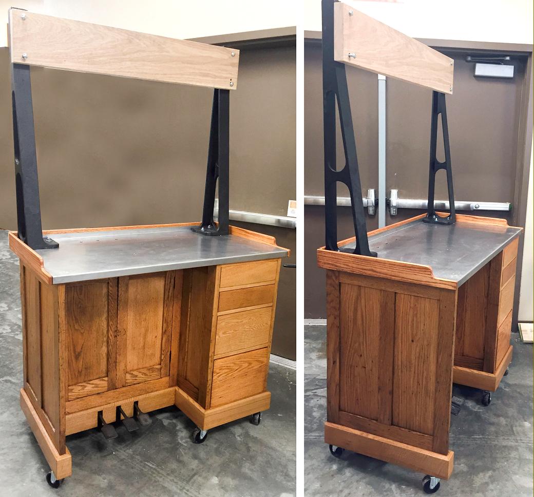
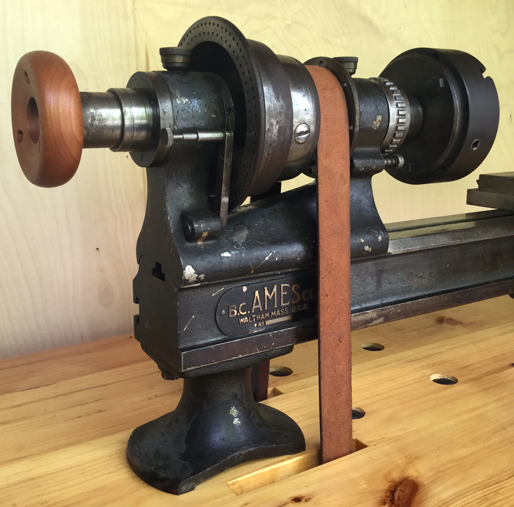
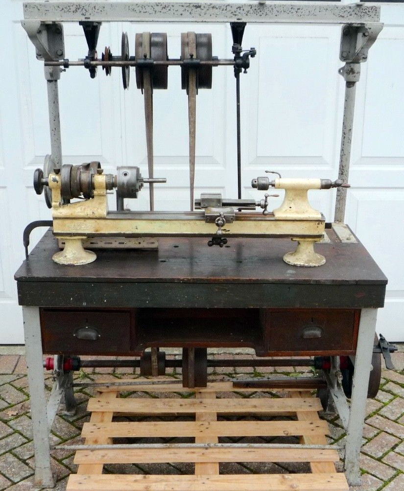
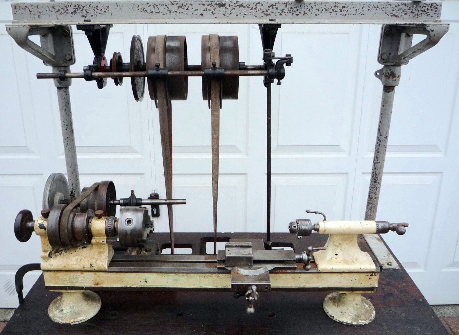
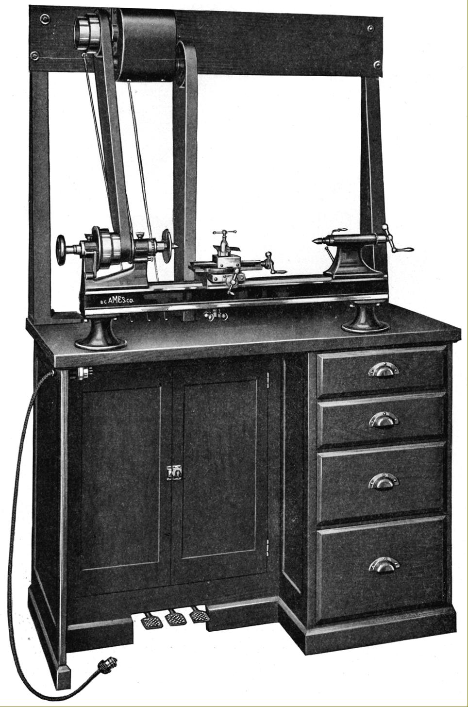
Early Ames No. 3 lathe on the oak cabinet stand with gearbox drive
As with other makers of lathes - both large and small - for decades Ames struggled to find a way of driving their machines in an efficient, compact and economical way. Probably the first to find a realistic solution was the American Atlas Press Company with their 1936 Model D - a replacement for their first effort, the 1931 9-inch with its over-complex and not terribly effective multi-B-belt drive arrangement. Ames lathes were, over several decades, offered with a variety of conventional wall and ceiling mounted flat-belt drive countershaft unit; wooden stands of various types with built-on metal frames to carry fast-and-loose pulley systems; very heavy, all- metal stands (in pressed steel of angle iron) with uprights to carry countershafts; stands with a combination of 2-speed gearboxes and belt drive from beneath and finally, as the Ames-Stark EH-3, on a variety of underdrive stands including one particularly neat example with variable-speed drive.
I addition to stands made by the factory, Ames also provided guidance drawings for customers to make up their own systems - an example is shown at the bottom of the page. One mount that appears to have been more common than the others - judging by the numbers surviving was a 48" long, 25" wide and 36" self-contained and rather elegant cabinet with either a 3-speed gearbox or 2-speed plus reverse. The stand was sturdily constructed from oak with a top surface edged with hardwood and covered in thick linoleum - an early form of plastic flooring very familiar to an "earlier generation". Two cast-iron uprights carried a cross member in hardwood on which was mounted the speed-change gearbox and, optionally, a drive for grinding and milling attachments carried on the lathe's top slide.
A 0.5 hp motor was fitted in the left-hand compartment, behind two doors, and the stand was either cut away on the right-hand side to allow space for the operator to sit down while working - or fitted with a nest of drawers. The motor drove upwards to the gearbox, the front of which was removable; inside the bronze casing were three sets of constantly-meshed helical gears, running within an oil-tight bath and each fitted with a heavily-built steel friction cone clutch that allowed an instantaneous change of speed. The drive from the motor entered from a 7" diameter pulley on the lower shaft and passed, via the gears and clutches, to an upper shaft that carried a cone pulley to match that of the lathe beneath it. Unusually for a countershaft of this era, the shafts ran on double-row ball races whilst the clutch thrust bearing was also of the ball bearing type.
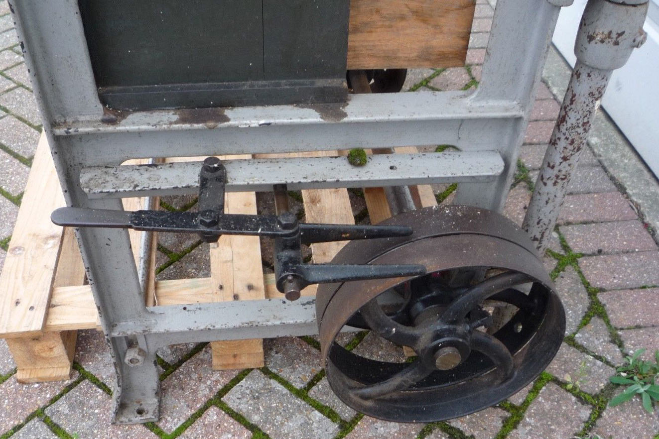
Controlled by foot pedals, the clutches were connected by wires to the engagement mechanism. Later stands were built on heavy, pressed steel legs with linoleum-covered, hard-wood faced wooden tops and used an underdrive system with either a 3-speed gearbox or a mechanical infinitely variable-speed unit.
An owner of an original stand writes:
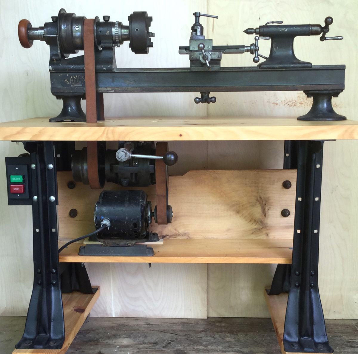
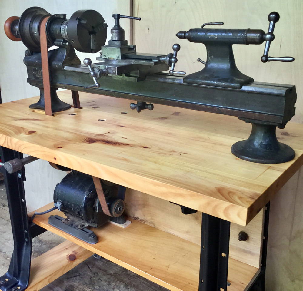
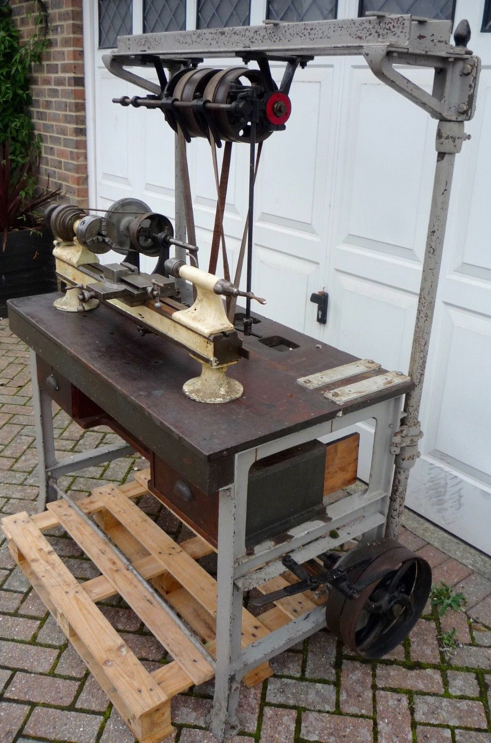
I recently found , after a long search, an Ames lathe (dated circa 1928) still mounted one its original oak bench; although externally the stand looked fine, internally it had been badly damaged and one must presume that the only reason it hadn't been reduced to firewood 40 years ago was it's tank-like build quality. Of course, the original the linoleum top was missing and had been replaced by several sheets of tacked-down roofing tin - this was replaced by some stainless steel that I had handy.
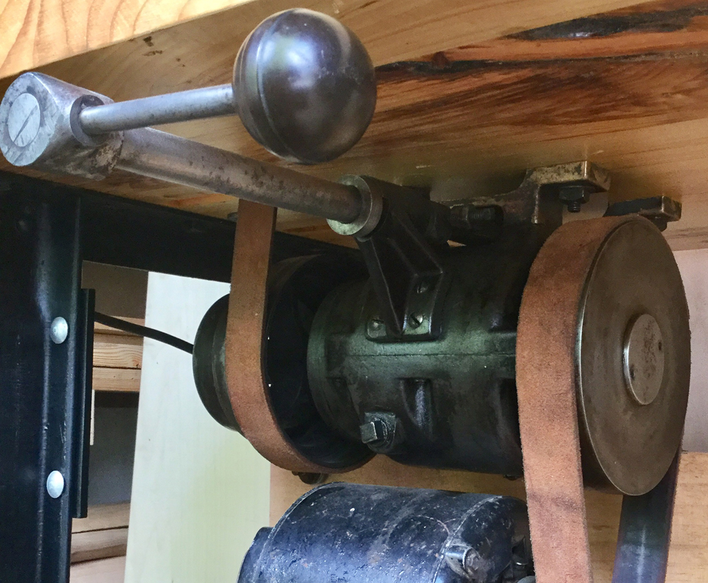
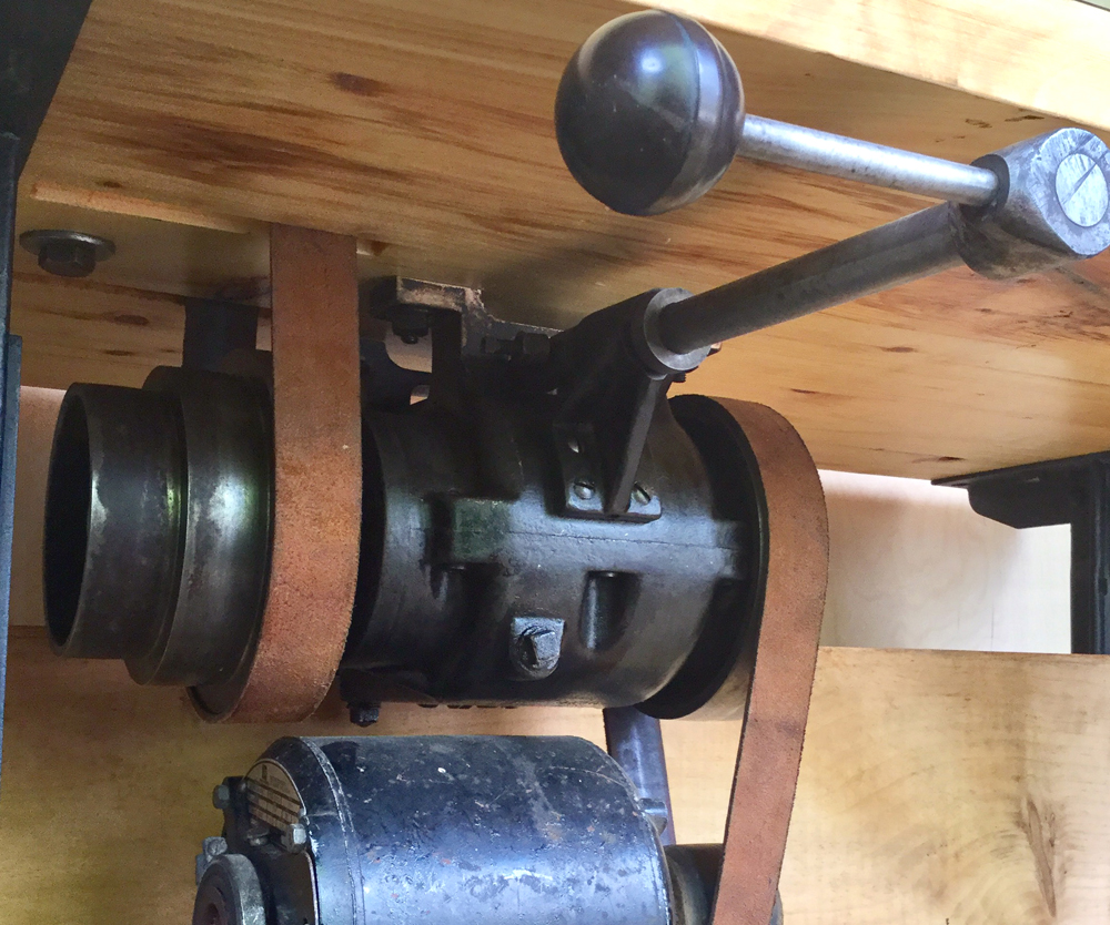
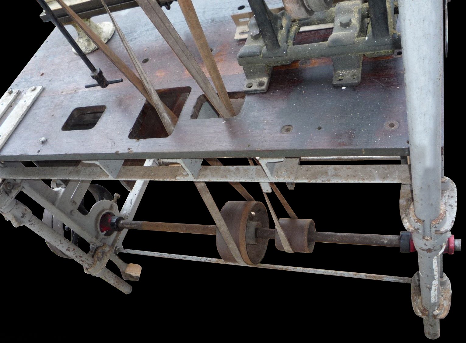
Fortunately the complex overhead drive transmission was complete and is currently being rebuilt - this mechanism including a 2-speed, plus reverse, constant-mesh gearbox with shafts running in ball races. On the back of the transmission system are control levers activated by cables that run three holes in the tabletop down to floor-level pedals. Unfortunately the original motor was missing, this being of a type - judging by the relationship between the holes for its mounting in the floor of the stand and that for the long flat belt to the gearbox - must have been rather weird. Possibly long and skinny with an extended drive shaft, or fitted to some sort of adjustable mounting system, the motor's location was dictated by the need to avoid the control cables, even then the makers even having to build a pulley rack to guide the control cables around it. I did some CAD modeling of the cabinet internals to see if a modern motor could be made to fit, but sadly it can't. However, the CAD work did tell me a couple of things: the "best fit" size for the drive pulley on the motor is roughly 4"OD . According to some of my sales literature, the driven pulley on the transmission was 7" OD so, assuming a 1725 RPM motor, that would give an input speed of 986 r.p.m. As the drive belt is 1.5" wide and the smallest step on the standard Ames flat-belt sheave is 4.19", it seems likely (to keep speeds within what might be expected for a lathe like this) that they may have used a similar size for the motor pulley.
I do have pictures and information from tearing down and rebuilding the transmission, but I'm not done with that yet and am trying to track down one of the bearings which, though still listed, are rare. Cast in bronze (no expense spared there) through with a rather rough external finish, the gearbox casing was painted in a prosaic gray..
|
|