|
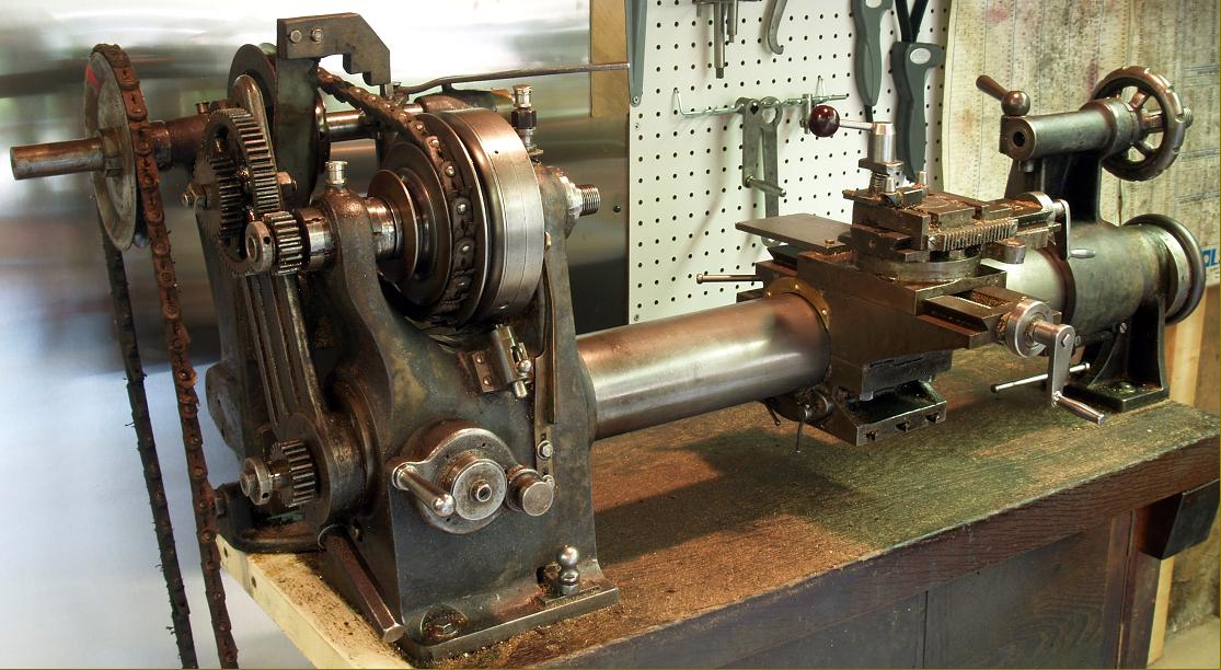
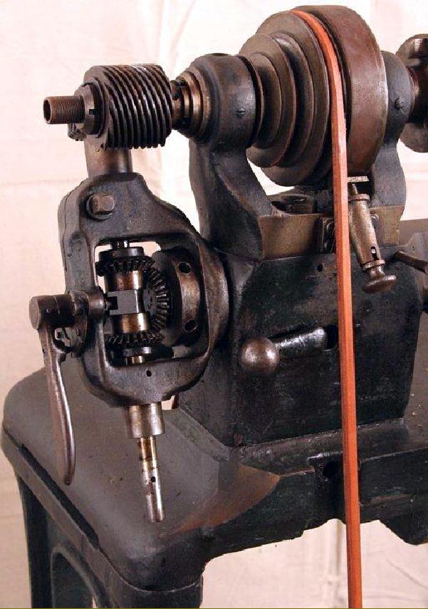
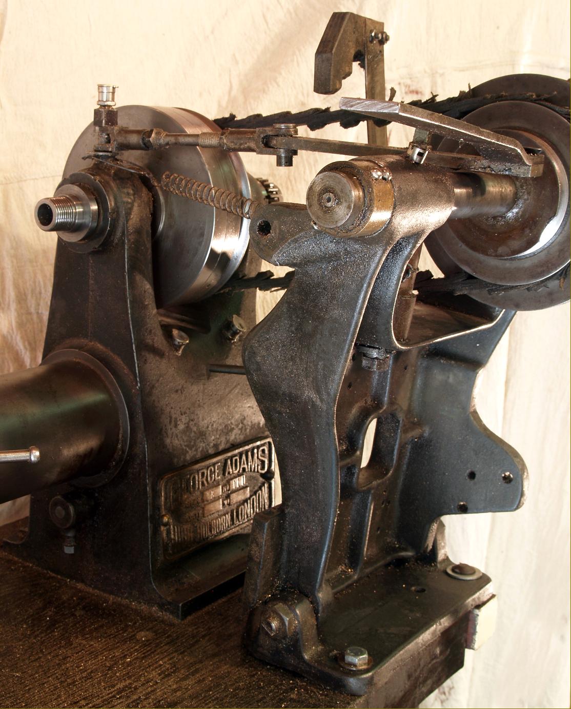
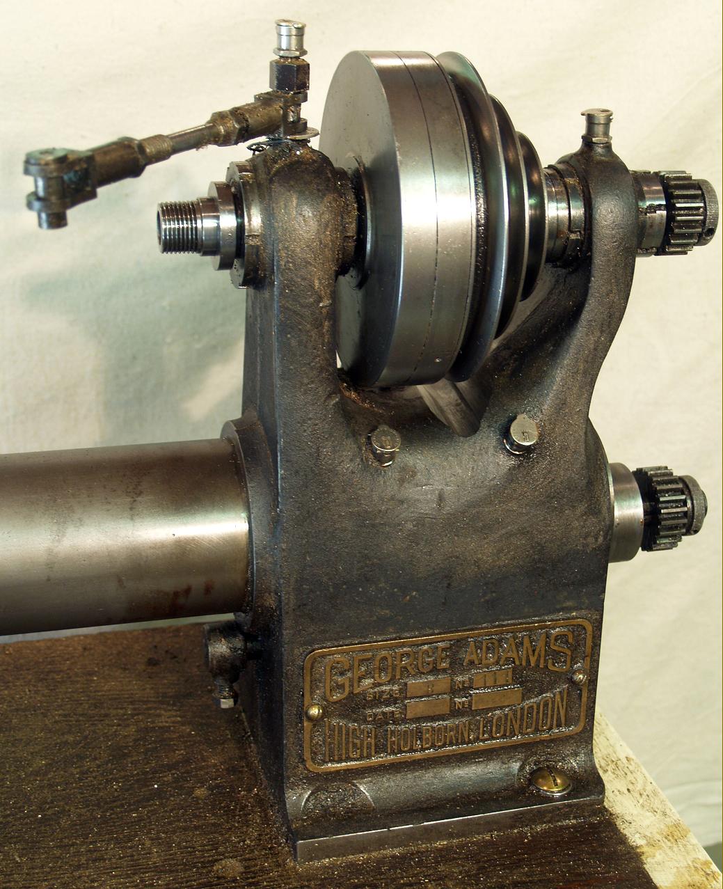
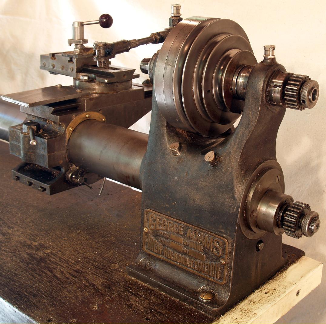
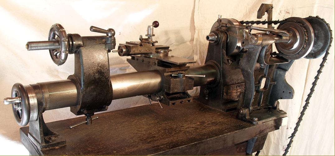
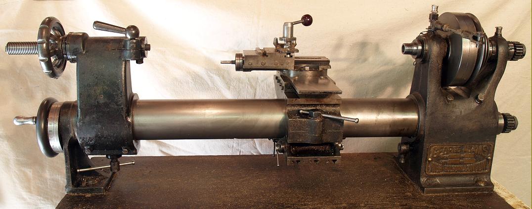
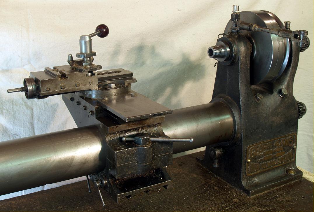
A most unusual machine and of very high quality, the George Adams 4" x 19.5" round-bed lathe is not often found; believed to have been introduced just before WW1, in 1913, production continued to an unknown date in the 1920s. Sometimes arranged for bench mounting, the makers also offered a very heavy, self-contained cast-iron plinth-like stand with a built-in treadle drive, the foot pedal being to the front in the normal way with the drive pulley overhung on the left-hand face; a picture of this assembly can be seen on this page.
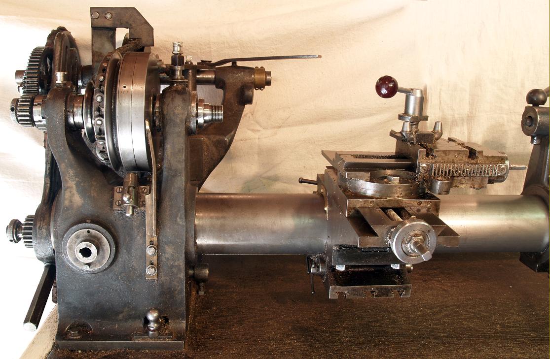
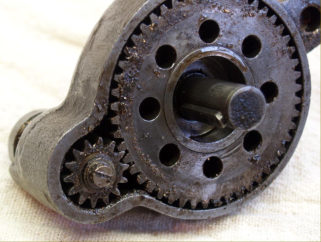
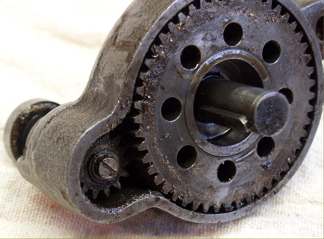
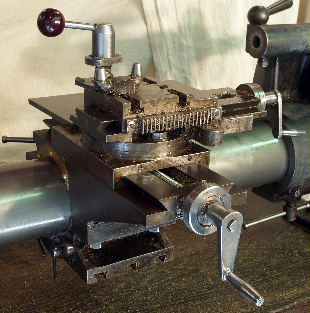
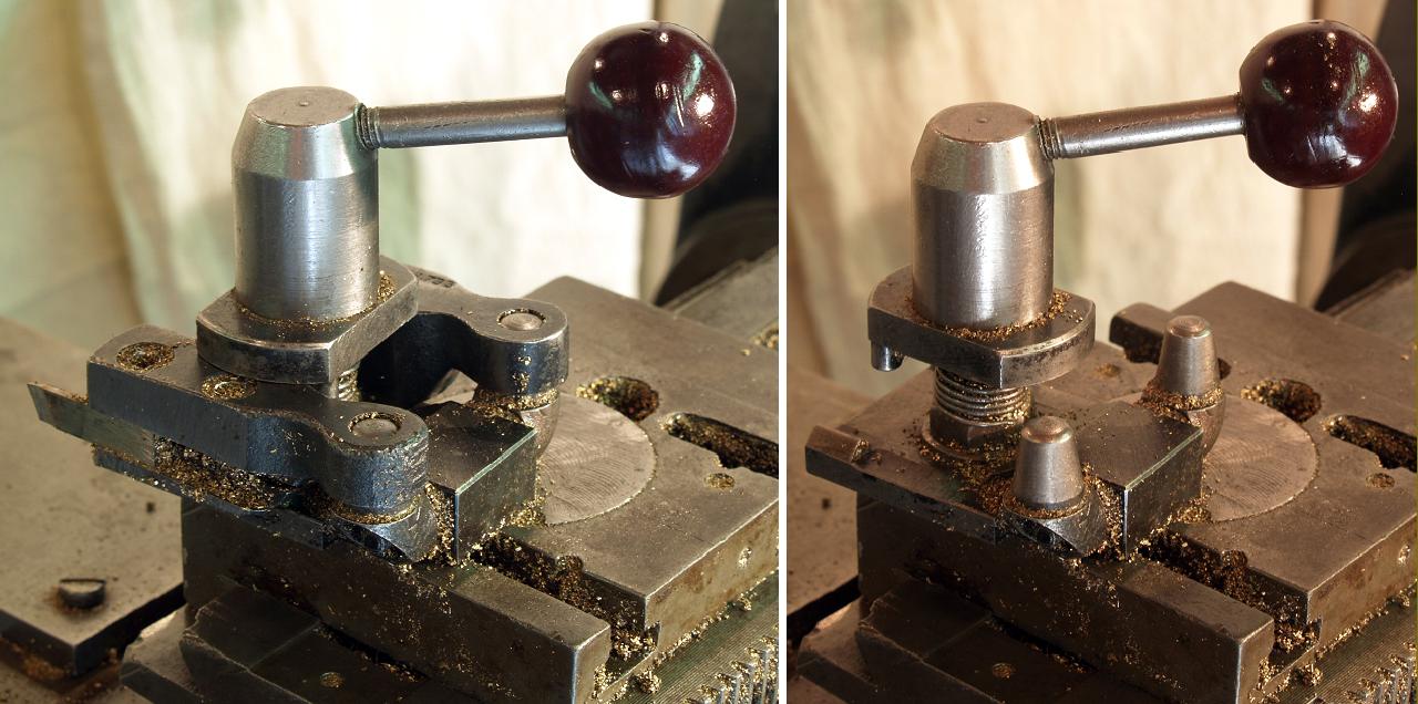
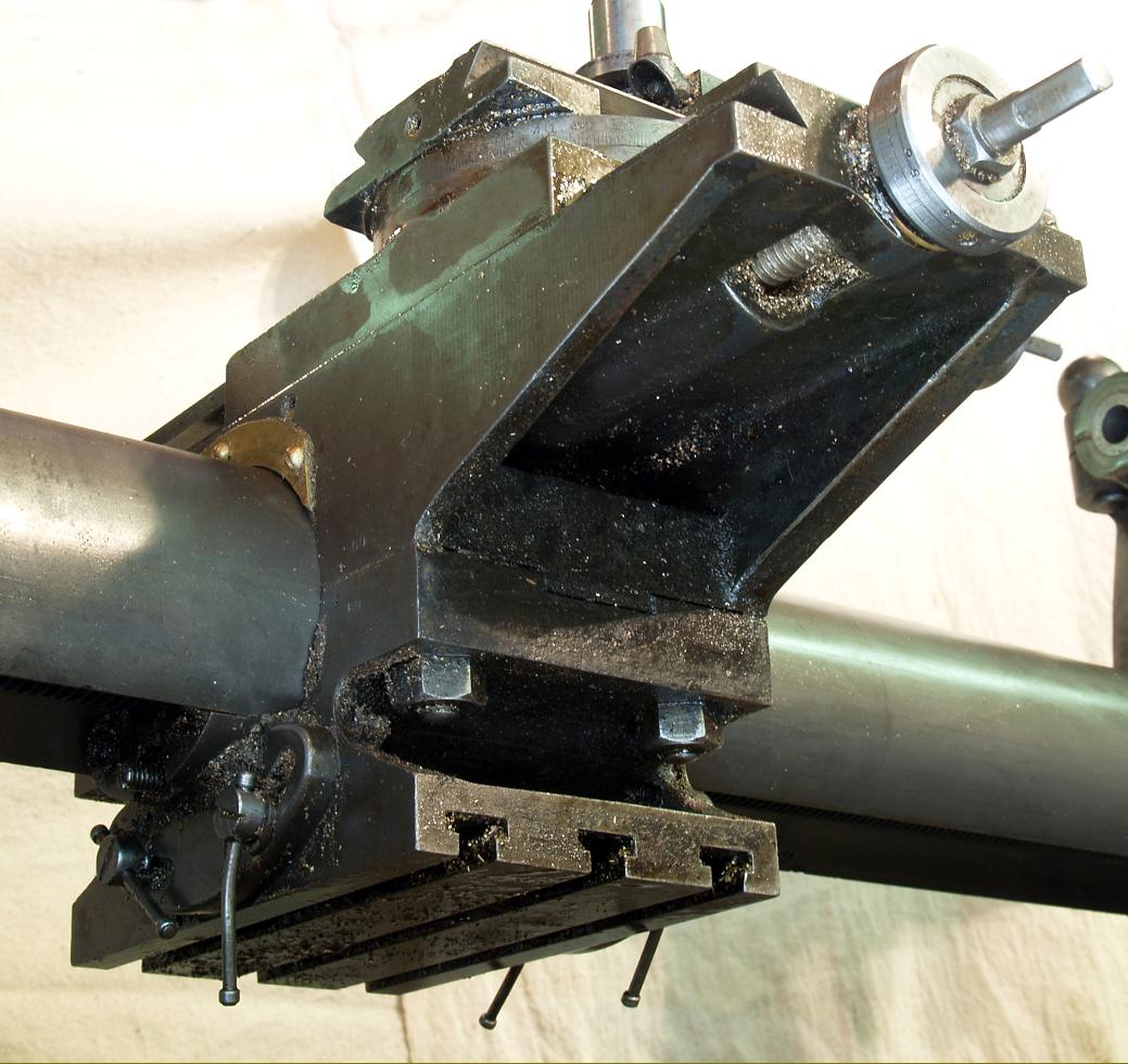
With a headstock bearing some similarity to that used on the Pittler B2 (for which Adams were the UK agents) it's possible that the round-bed was manufactured by the English firm of Milnes - some Pittler lathes being built by them either officially, under licence, or merely copied. As the versatile Pittler would have been an expensive lathe to engineer and clone perhaps George Adams, looking for similar functionality, retained the compact, Pittler-type epicyclic backgear (built into the largest diameter of the headstock pulley), but simplified other matters with a round instead of trapezoidal bed. Like the Pittler, the George Adams round-bed was able to rotate the complete carriage around the bed - but in this case instead of only partially, it could be turned through 180° to bring a permanently-mounted, T-slotting boring table to the top while leaving the complete compound slide rest undisturbed. In addition the lathe has a number of other interesting features including, Mounted on the front face of the headstock was a handwheel by which means the carriage could be moved along the bed. Interestingly, this could be operated in two ways, either with a direct drive at a ratio of 1 : 1 or though built-in reduction gearing that gave a carriage advance of 0.010" per revolution. Inside the handwheel was a pair of gears, one small the other large, with the former connected to a push button that allowed it to be engaged and disengaged. When engaged the pair of gears acted as an epicyclic - though of course for this to happen the larger gear had to be locked in place, this being achieved by a peg on the handwheel-mount engaging a hole in the larger gear. With the gears engaged and the larger gear locked, when the assembly was rotated the reduction in ratio was obtained.
In practice users found that the 1 : 1 ratio was difficult to use: the handle being too small and the torque needed to turn it considerable. However, the reduction mechanism worked perfectly and was the one used most of the time; if a faster rate of feed was needed, for example to reposition the carriage quickly, the large handwheel at the tailstock end of the leadscrew worked with ease.
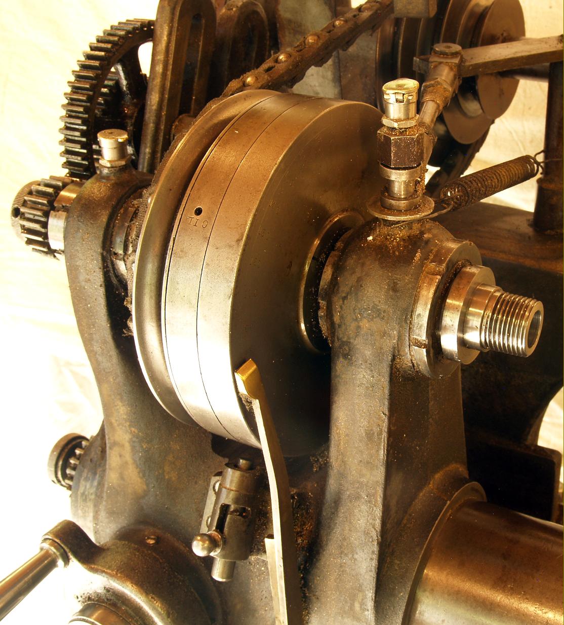
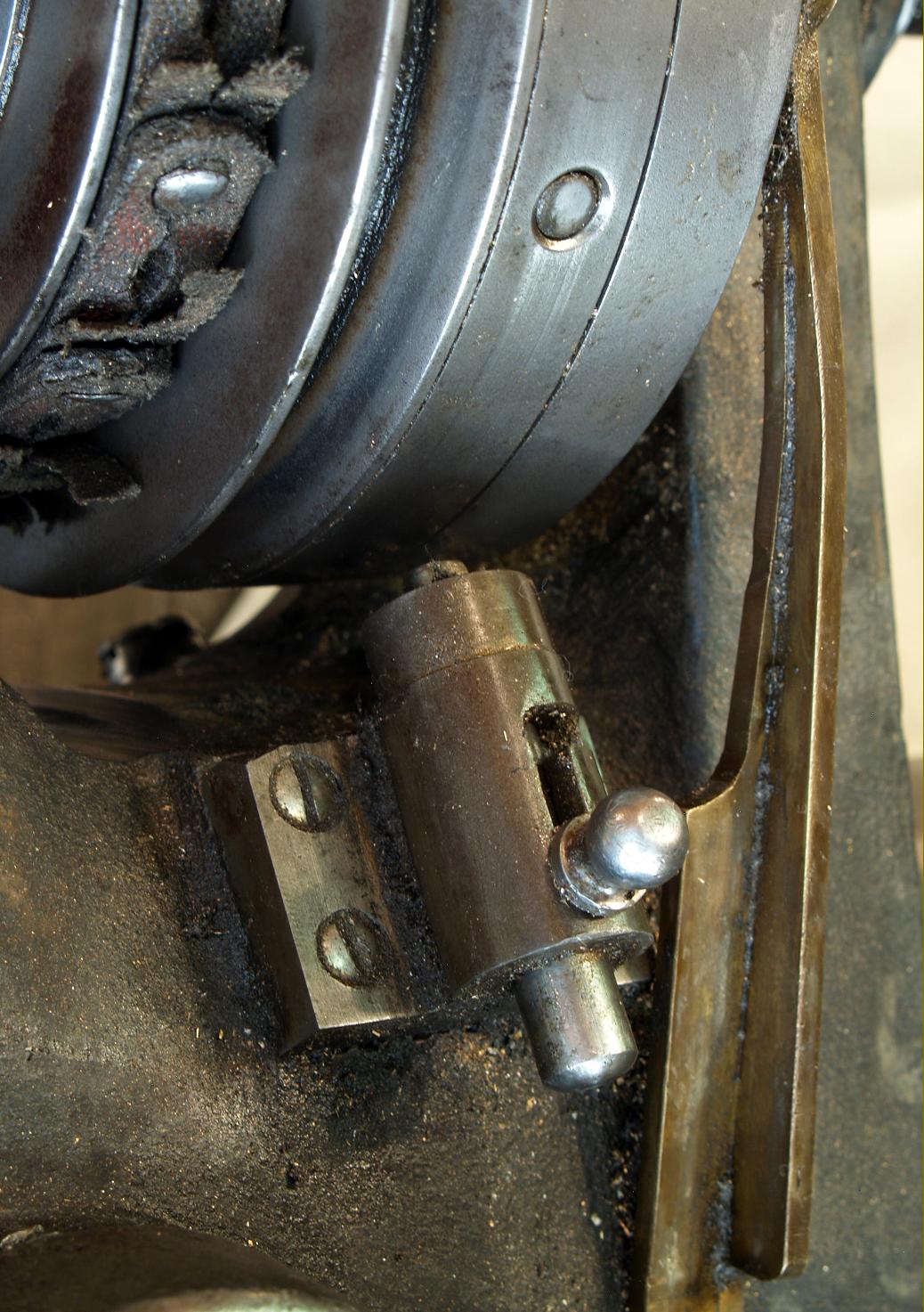
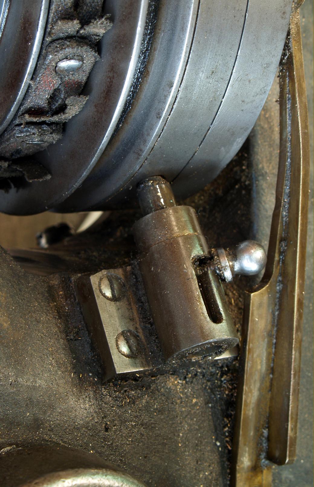
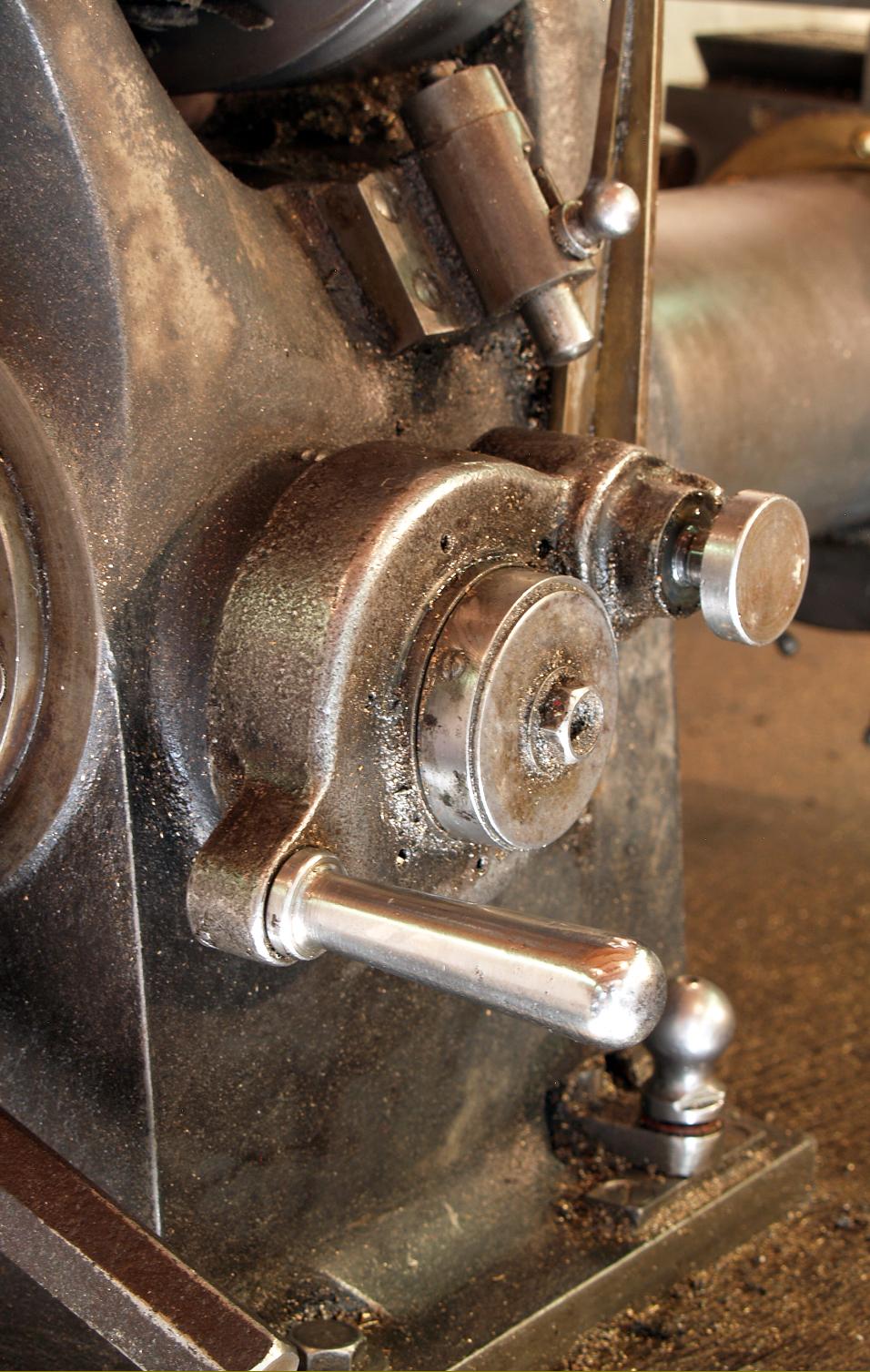
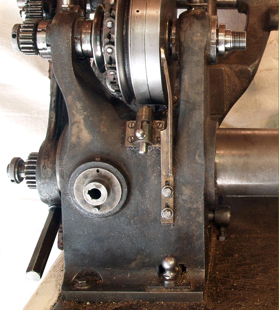
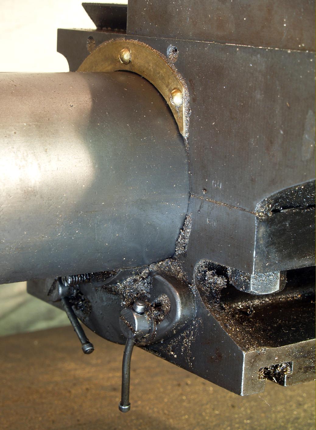
To engage, disengage and reverse the hand-feed feed a sliding knob was provided at the front base of the headstock; sliding the knob to the right caused the carriage to advance towards the headstock when the handwheel was turned anti-clockwise (and vice-versa). Setting the knob to the left reversed the motion so that turning the handwheel anti-clockwise moved the carriage away from the headstock (and vice-versa). With the knob in the central position the leadscrew was disengaged and could then be turned by the tailstock-end handwheel. The same sliding mechanism also engaged the screwcutting feed between the changewheel train and the leadscrew - two oil caps at the back of the headstock allowing lubrication of the internal gears that connected everything together. In addition the lathe was also fitted with an automatic disengage to the carriage drive - a rod being attached to the slider that engaged and disengaged the leadscrew feed. With the slider pushed to the right and the screwcutting (power) feed operating, the rod and slider moved out together towards the carriage and, when contact was made, the carriage pushed the slider back to its central position and so disengaged the drive. In theory it would have been possible to add extensions to the disengagement rod using and screwcut for a fixed distance or up to a shoulder - though for safety this would have need a slow spindle speed and care in setting up. While lathes of this type and class are frequently found with some sort of indexing arrangement on the headstock - usually one or more circles of holes drilled into the front face of the headstock pulley with an indent pin for registration - the George Adams arrangement was different with the flat front face of the largest headstock pulley inscribed every 10° with a line. Bearing against the face, and providing a reference point, was the flatted tip of a bronze bar bolted, at its lower end, to the outside face of the headstock. Thus equipped, it was possible for a turner to index the spindle to a chosen poition - but not lock it..
|
|