email: tony@lathes.co.uk
Home   Machine Tool Archive   Machine-tools Sale & Wanted
Machine Tool Manuals   Catalogues   Belts   Books  Accessories

Milnes Lathes

Milnes R-Type  Very Early Milnes Lathe    Milnes 1920s    Milnes 13" Photographs
Milnes Milling Machine    Milnes Planer    Milnes DF-4 Lathe (Denham)


A detailed handbook for the 13-inch swing lathe
illustrated below is available together with other Milnes literature

Henry Miles of Bradford built mainly lathes - though also some planers and milling machines -  from 1858 until the 1970s - indeed, until the late 1990s, a spares service still existed for the more recent models. The early lathes, all smaller models up to five inches in centre height, evolved gradually with improvements and changes in specification introduced only sparingly. However, by the early 1930s, larger, heavier and genuinely industrial machines had become a core part of the company's business and interest in producing smaller models waned. All Milnes lathes were well built - with even the now antique versions intended for amateur and light workshop use having proper horn handles on the control levers and displaying an exemplary standard of fit and finish. Some badge engineering also went on: an example being the popular Denham Junior lathe sold as the Milnes Type DF-4
One of the company's most popular and enduring lathes was the geared-headstock 13-inch swing model. Made from shortly after WW2 until the early 1970s it was, for its limited capacity, an expensive proposition, the price of £1185 (in 1961) being almost two-and-a-half times that asked for a 6" x 40" Harrison lathe of only slightly inferior specification - and only a few pounds less than the massive 8.5-inch centre-height Harrison L17 which, with a  3" hole through its sturdy L.2 taper nose spindle, was able to accept a bar some 1 3/8" greater in diameter than that (15/8") that could be persuaded to pass through the old-fashioned 2.5" x 4 t.p.i threaded spindle of the Milnes. The 12 speeds of the 10HP Harrison started at the same level, 32 rpm for the Harrison and 30 rpm for the Milnes, but then the former went on to spin, at 1700 rpm, exactly twice as fast as the latter..
Despite these on-paper drawbacks, the Milnes 13-inch was an exceptionally well-made lathe and had a reputation for accuracy over a very long life. The hardened bed featured a detachable gap (capacity 20-inches in diameter) that could be ordered in an extra-long 72"-capacity version complete with a central supporting column. 
Continued below:

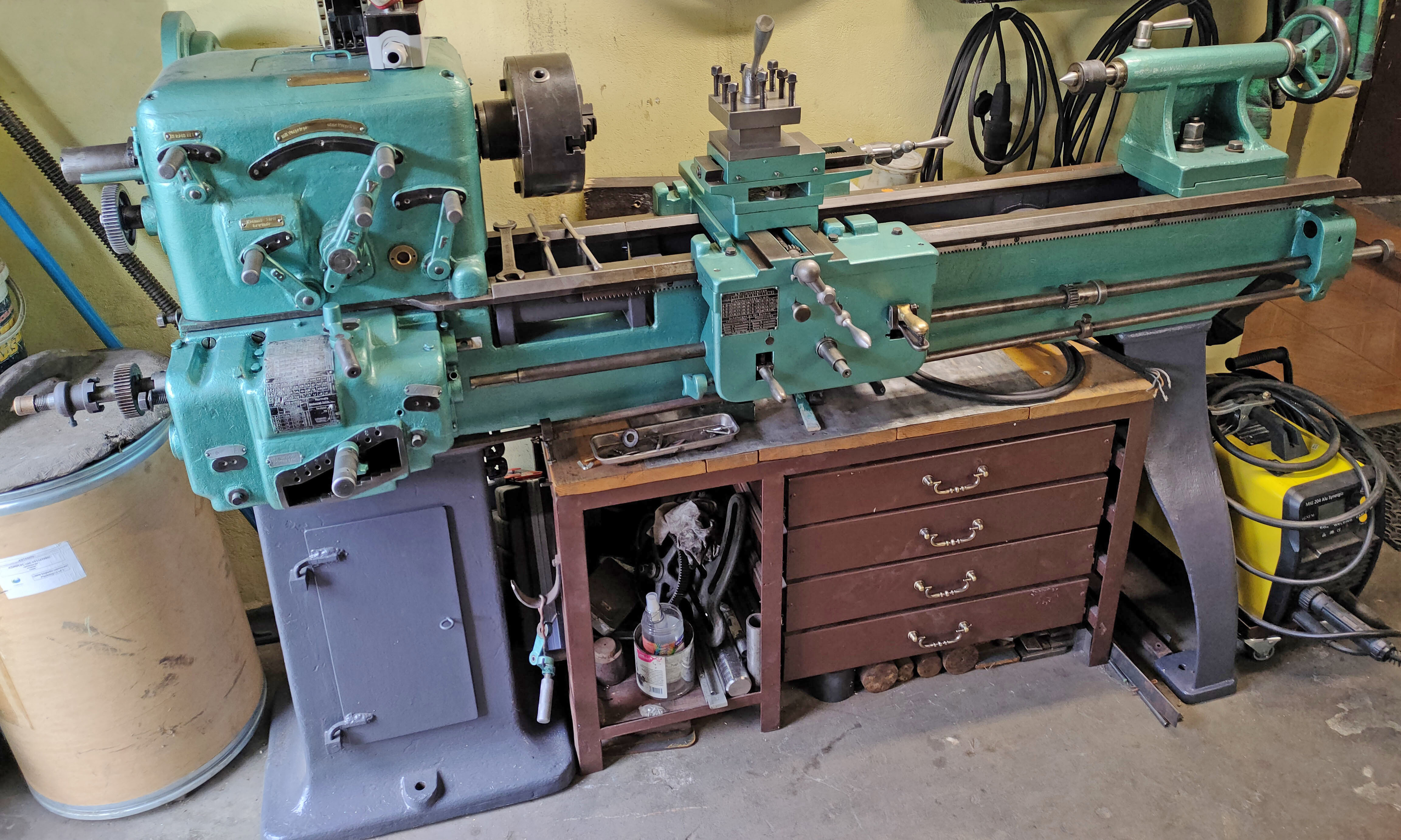
The expensive but very well built Milnes 13-inch swing lathe. This is a specially-prepared show machine with extensive frosting to the front of the apron and even to the faces of the 4-way toolpost.

Continued:
Although all early models had the No. 5 Morse taper headstock spindle running in plain parallel-bore, taper-outside phosphor bronze bearings, later models were offered with the option of Timken taper-roller races. The headstock gears were manufactured from carbon-chrome alloy steel with 0.55/0.65% carbon, 0.3% silicon, 0.5/0/8% manganese and 0.45/0.7% chromium. Driven by 2 V-belts from a 2-h.p. 3-phase motor the rather slow spindle speeds of 30, 47, 77, 126, 179, 284, 463 and 750 rpm were controlled by three levers, mounted on the front face of the headstock and moving through quadrant arcs. The lever on the right selected either the high or low speed ranges whilst the two on the left (interlocked to prevent two gears being engaged at once) controlled  the 4 individual speeds in each range. The headstock contained a multi-plate reversing clutch that could be operated, through a third-shaft control rod, from either a lever connected to a bevel box just to the right of the screwcutting gearbox or a rod pivoting from the right-hand face of the apron. Whilst the headstock gears relied on an inexpensive and simple splash system for lubrication the clutch, which was under considerable stain, was provided with its own pumped supply.
Equipped as standard with a conventional "Norton" pattern quick-change gearbox, the lathe could generate 27 pitches and feeds with a further 27 available by the simple expedient of swapping over two gears on the drive arm.  A range of other changewheels (with a 20-degree pressure angle) was supplied to allow a wide range of metric pitches to be generated, these included: 30t, 45t, 55t, 60t, 65t, 70t, 75t, 120t and 127t. The 11/8-inch diameter 4 t.p.i Acme-thread leadscrew was fitted with a dog-clutch at its headstock end and was normally left disengaged. The power shaft drive was protected by a strong spring-assisted "over-ride clutch" held inside a sleeve where the shaft entered the gearbox.
Of conventional design the apron used worm-and-wheel gearing,  driven by a slotted, key-carrying power shaft that transmitted drive to a train of gears that could be directed to give either power sliding or power surfacing. Selection of the feed direction was by lifting or lowering a centrally-mounted quadrant lever and engagement by a concentrically-mounted a screw-in-and-out knob that engaged a cone clutch.. Sliding power feeds varied from 0.002" to 0.036" per revolution of the spindle with the surfacing rate set at 1/3 of the same range. The top of each rather narrow saddle wing was fitted with T slots that allowed the travelling steady to be given a wide and hence stable base. The compound slide rest was fitted with proper tapered gip strips and the cross and top slide travels were 81/2-inches and  63/4" respectively, both driven by a respectably-large 5/8"-diameter 8 t.p.i Acme-form feed screws; however, on the machines illustrated, the micrometer dials were far too small.
15/8-inches in diameter, the tailstock  barrel was fitted with a No. 3 Morse taper; it's five inches of travel were marked by engraved lines and drive was by a 3/4-inch diameter left-hand Acme-form thread.  Unfortunately the nut used to clamp the tailstock to the bed required the use of a loose, self-hiding spanner.
As supplied from the factory the lathe was equipped with: the main driving motor, switchgear and belts, fixed and travelling steadies, a thread-dial indicator, 4-way toolpost, an electric suds pump and receiver tank, faceplate, catchplate, changewheels for metric screwcutting, a rear splash guard, one pair of headstock and tailstock centres and oil gun and instruction book.
With an overall length of 83-inches long the standard model weighed 16 cwt (1792 lbs/812 Kg) whilst the long-bed version was 1161/2" long and weighed, at 20 cwt (2240 lbs/1016 kg) some 25% more..

The 6.5" x 72" model - a genuinely long-bed lathe the bed of which required a central support plinth

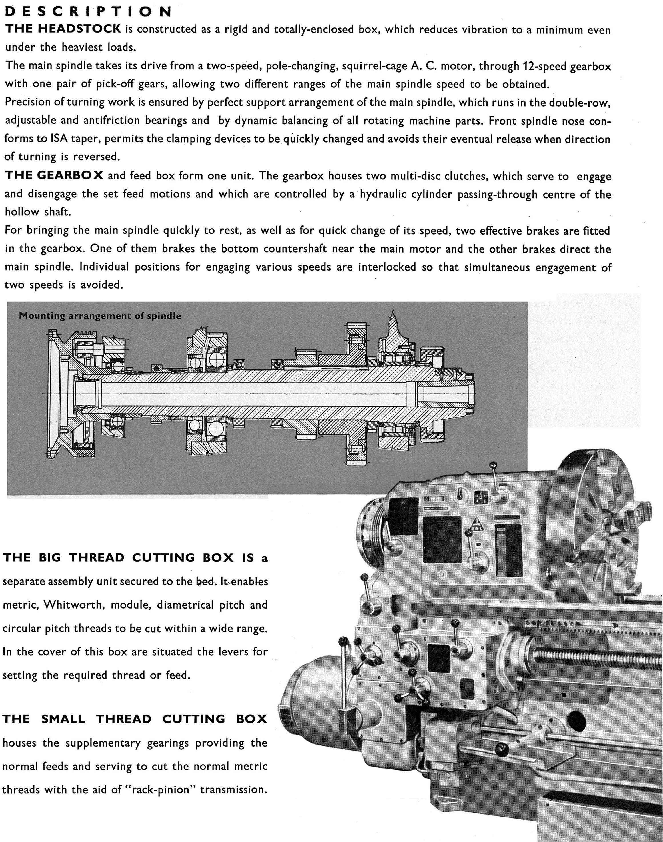
Although all early models had plain parallel-bore bronze bearing later models were offered with the option of Timken taper roller races. Spindle speeds were controlled by three levers moving through arc's. That on the right selected the high-low speed range whilst the two on the left (interlocked to prevent two gears being engaged at once) engaged the 4 individual speeds in each range. The headstock contained a reversing clutch working through a third-shaft control rod that could be operated either from a lever connected to a bevel box (just to the right of the screwcutting gearbox) or by a rod pivoting from the right-hand face of the apron.

Screwcutting and feeds: the conventional "Norton" pattern quick-change gearbox could generate 27 pitches and feeds with a further 27 available by the simple expedient of swapping over two gears on the drive arm. The leadscrew was fitted with a dog-clutch at the headstock end (the knurled edge of its operating ring can be seen in the picture above) and was normally left disengaged. The power shaft drive was protected by a strong spring-assisted "over-ride clutch" held inside a sleeve where the shaft entered the gearbox. The lowest shaft - the "third-lever control" - controlled the clutch used to start, stop and reverse the spindle.

Of conventional design the apron used worm-and-wheel gearing,  driven by means of a slotted, key-carrying power shaft, to transmit drive to a train of gears that could be directed to give either power sliding or power surfacing. Selection of the feed direction was by lifting or lowering a centrally-mounted quadrant lever and engagement by a concentrically-mounted a screw-in-and-out knob that engaged a cone clutch.
The top of each rather narrow saddle wing was fitted with T slots that allowed the travelling steady to be given a wide and hence stable base.

The compound slide rest, fitted with proper tapered gip strips, had cross and top slide travels of 81/2" and  63/4" respectively both driven by a respectably large 5/8"-diameter 8 t.p.i Acme-form feed screws. However, on the early machine illustrated, the micrometer dials were far too small.

Although all early models had the headstock spindle running in plain, parallel-bore, tapered-outside bronze bearings later models were offered with the option of Timken taper roller races.

The bevel box by which means the action of third-shaft control rod was made to pass through the bed and engage with the rear-mounted headstock clutch lever.

Milnes 13-inch headstock spindle multi-disc, oil-immersed clutch

Milnes 13" Photographs

Milnes R-Type  Very Early Milnes Lathe    Milnes 1920s   

Milnes Milling Machine    Milnes Planer    Milnes DF-4 Lathe (Denham)

A detailed handbook for the 13-inch swing lathe
illustrated below is available together with other Milnes literature


Milnes Lathes
email: tony@lathes.co.uk
Home   Machine Tool Archive   Machine-tools Sale & Wanted
Machine Tool Manuals   Catalogues   Belts   Books  Accessories