 |
|
|
|
|
|
|
|
|
|
|
|
|
|
|
|
|
|
|
|
|
|
|
|
|
|
|
|
|
|
|
|
|
|
|
|
|
|
|
|
|
|
|
|
|
|
|
|
|
|
|
|
|
|
|
|
|
|
|
|
|
|
|
|
|
|
|
|
|
|
|
|
|
|
|
|
|
|
|
|
|
|
|
|
email: tony@lathes.co.uk
Home Machine Tool Archive Machine-tools Sale & Wanted
Machine Tool Manuals Catalogues Belts Books Accessories
CROMWELL LATHE Mk. 2
Cromwell Home Page Mk. 1 Cromwell Plain Lathe
Smallpiece Multi-cut Lathe
Rebuilt Cromwell S800 Mk. 2 Screwcutting Cromwell
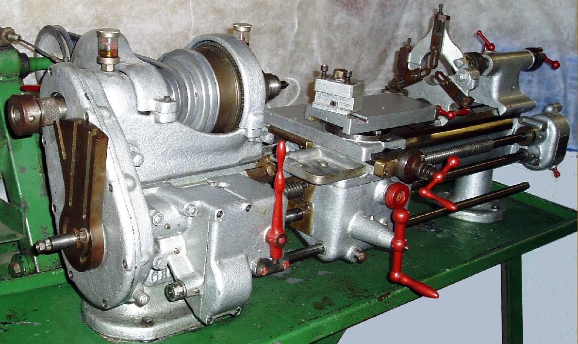
Produced as both a plain-turning precision lathe and, as shown on this page, a backgeared and screwcutting model, the 3.5" x 20" Mk. 2 Cromwell is more often to be found mounted on a very heavy cast-iron stand with the words Cromwell Coventry cast into its front face. While the headstock, compound slide rest and tailstock resembled those on the simple Mk. 1 this was a very much more complex machine with the screwcutting and power sliding and surfacing feeds arranged in an unbelievably convoluted and expensive-to-produce way - and quite unlike that on any other lathe seen by the writer. As far as can be understood, the system used two separate back-to-back gear trains at the headstock end, a second gearbox by the tailstock, a permanently-engaged leadscrew for screwcutting and two powershafts - one for sliding (with final drive via the leadscrew) and the other for power cross feed. At the headstock end of the lathe one fixed-ratio gear train was enclosed in a housing and used for power feeds while the other was carried externally - and unprotected - and employed only for screwcutting. The changewheels were carried on square-ended studs that slotted into a beautifully-made quadrant arm with precisely machined T-slots. Only one train of gears could be driven at once and relied upon the operator taking off and reversing a gear fitted to the end of the headstock spindle. In order to achieve a drive from two gearboxes (they used a common output shaft) the lowest (bronze) gear within the reduction box was pinned to a large diameter, hollow bronze shaft with a gear cut at its furthest end. Passing through the bronze shaft was a steel bar keyed, in the usual way, to the lowest gear of the screwcutting changewheel train. The concentric bronze and steel shafts emerged into a second "Selector Gearbox" where the bronze gear drove a train of gears (used to power the sliding and surfacing feeds) that turned both the steel shaft and 4 t.p.i. leadscrew. A lever on the front face of the Selector Box was arranged to operate separate dog clutches for the sliding and screwcutting feeds - the surfacing feed being in permanent engagement. When moved to the right the lever set the rate of longitudinal feed shown on the tailstock-end gearbox cover, the central position providing a neutral and the left-hand position the screwcutting feed. Because the drive from the reduction box was at a fixed ratio, in order to provide a variety of sliding speeds the powershaft passed though the apron and drove a reduction "pick-off" gearbox at the tailstock end of the bed. This box, supplied with a selection of six gears arranged in pairs, gave six rates of feed (a plate on the box showed how to arrange the gears) and drove the leadscrew. The tailstock-end box used gears of the same pitch (16DP) as the later models - but with a smaller centre hole. An additional fixed-ratio sliding feed was also achieved by arranging for the slotted powershaft to drive a gear in the apron that meshed with the carriage-traverse handwheel shaft. The lower power shaft was overhung at its right-hand end and, as it passed through the apron, drove a bronze worm and wheel - the latter with a cone clutch formed in its centre into which was pushed, by a knurled-edge knob on the face of the apron, a steel gear that meshed with a gear on the cross-feed screw Unfortunately, when the clutch faces became, it became impossible to apply enough pressure to keep the drive engaged. Just one rate of power cross feed was provided - and in an outwards direction only.
While the main elements of the Mk. 2 - bed, carriage and tailstock - were almost identical to those used on the Mk. 3 (the S800) the headstock was completely different and carried either a 3-speed flat belt or 4-speed V-belt pulley. The spindle end, though it resembled that on the S800 in having twin registers to support backplates and faceplates, had different dimensions: a 13/8" outer parallel register, a 15/8" by 12 t.p.i thread and a 13/4" parallel register. A conventional eccentric-shaft backgear assembly was provided with a nut and sliding dog to uncouple the bull gear from the spindle pulley. Like both earlier and later versions, the headstock spindle ran in a pair of adjustable, draw-in bronze bearings (or white-metal bushes by Glacier) tapered on their outer surface.
Alternative top slides appear to have been offered-- some machines being found with one identical to the type, with exposed slideways and two T-slots, used by Boley on their pre-WW2 Model 3L and 4L lathes; this unit needed a cross slide formed with a semi-circular support flange on its right hand side. Other lathes had an entirely different arrangement with the slide having covered ways and a single T-slot. While the twin-slot top slide was a copy, the single-slot was entirely original for, although a normal V-edge was used, with a gib strip, instead of the base casting being flanged for the upper casting to run on, the roof of the upper casting was employed instead - a most unusual arrangement. The tailstock was given a separate sole plate that allowed the top to be set-over for taper turning.
If you have a Mk. 2 Cromwell lathe of any type, the writer would be pleased to hear from you. .
|
|
|
|
|
|
|
|
|
|
|
|
|
|
|
|
|
|
|
|
|
|
|
|
|
|
|
|
|
|
|
|
|
|
|
|
|
|
|
|
|
|
|
|
|
|
|
|
|
|
|
|
|
|
|
|
|
|
|
|
|
|
|
|
|
|
 |
|
|
|
|
|
|
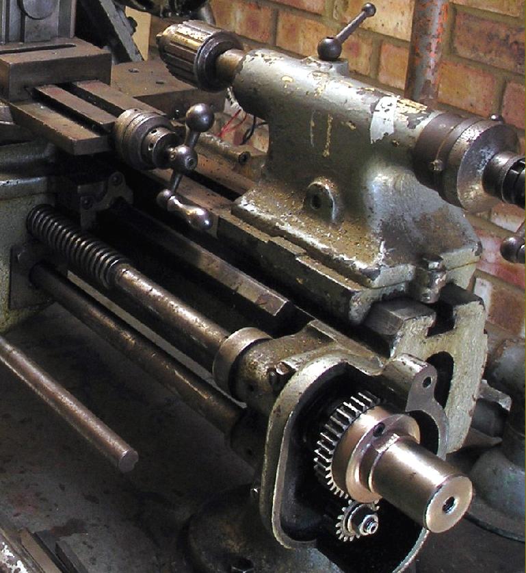
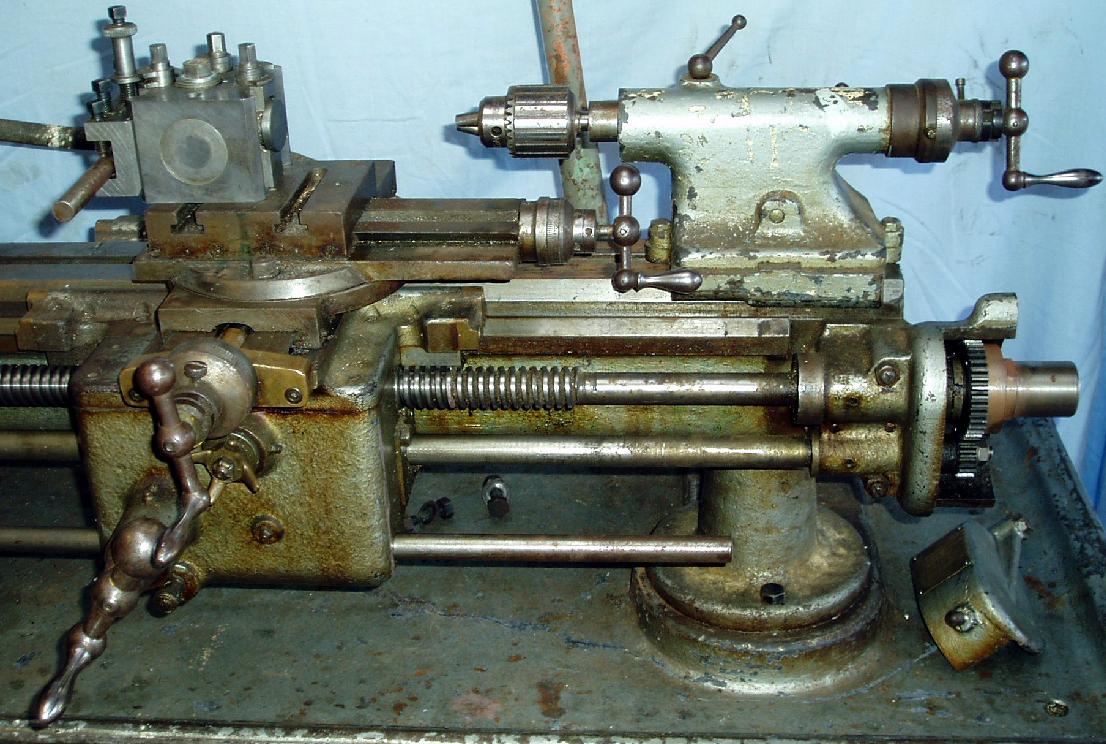
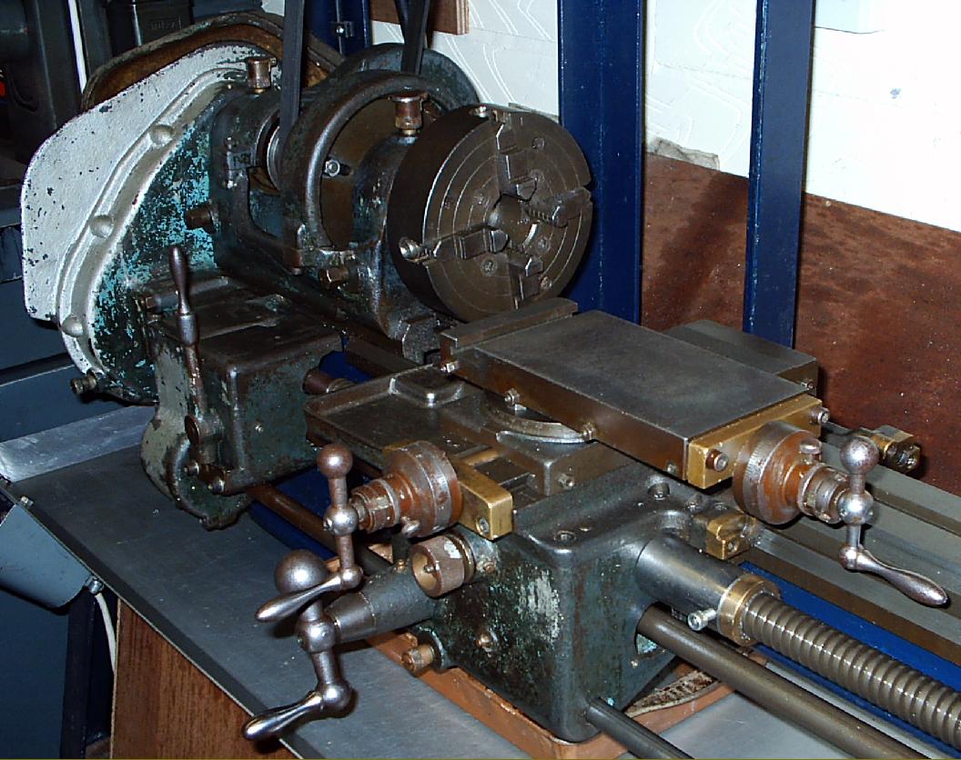
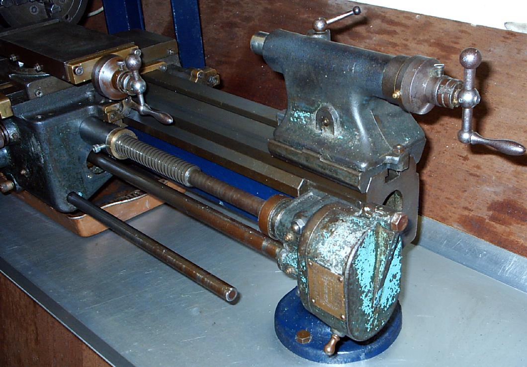
Mk. 2 Cromwell with backgear, screwcutting and power sliding and surfacing feeds. Note the tailstock-end mounted feeds' gearbox with its swing-up cover, the overhung power cross-feed shaft and compound slide rest end plates in bronze.
|
|
|
|
|
|
|
 |
|
|
|
|
|
|
|
|
|
 |
|
|
|
|
|
|
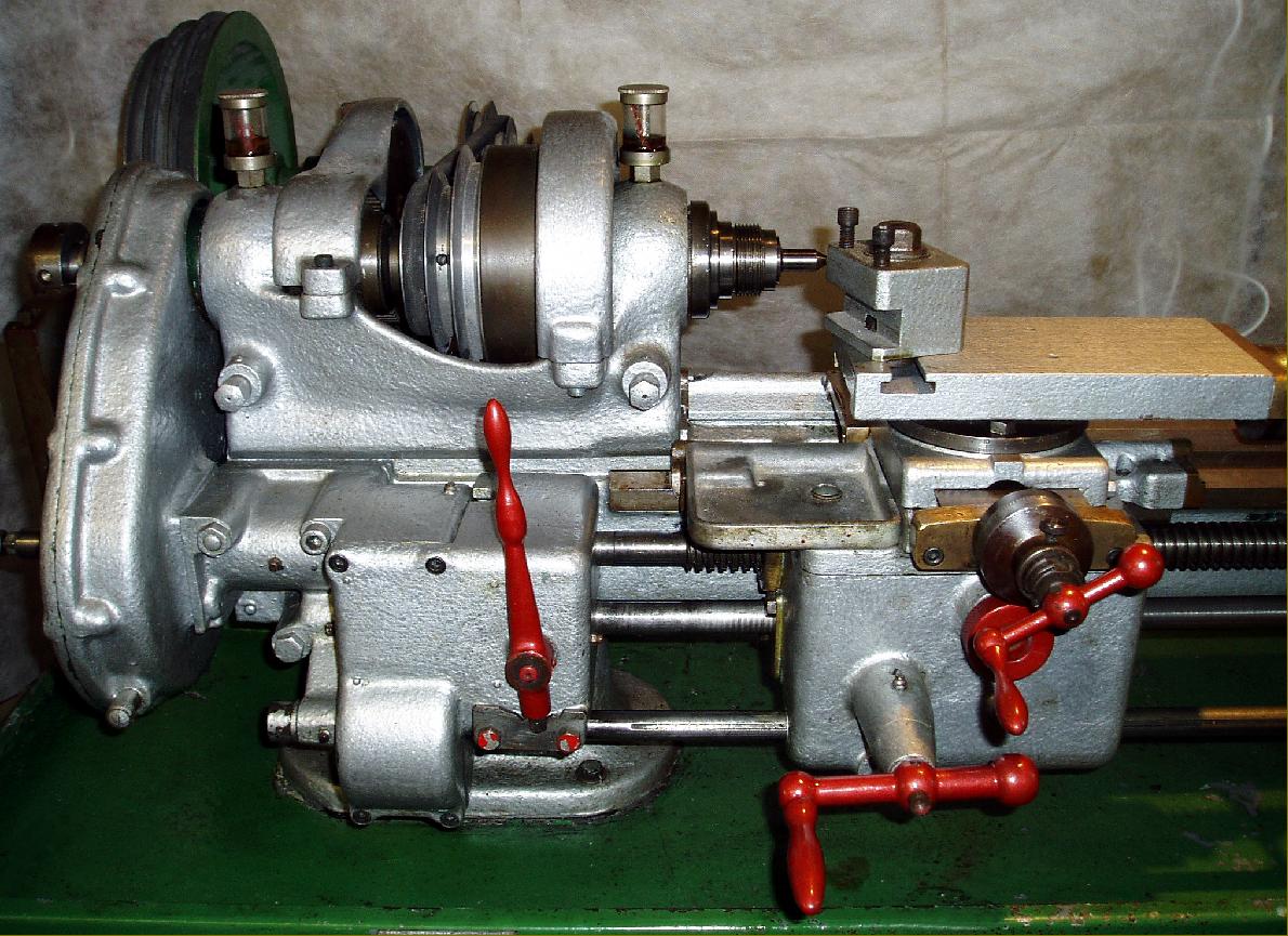
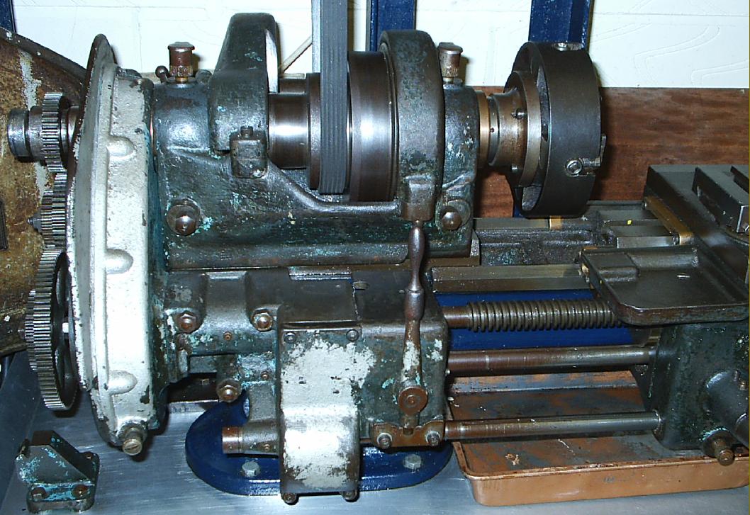
The single lever immediately below the headstock operated individual dog clutches that engaged either screwcutting or the power sliding feed. Its central position provided a neutral with neither engaged
|
|
|
|
|
|
|
 |
|
|
|
|
|
|
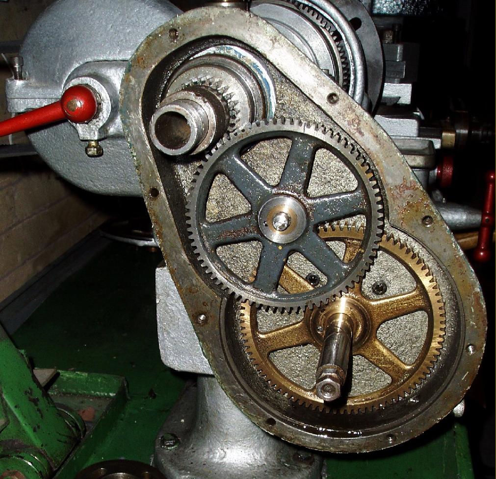
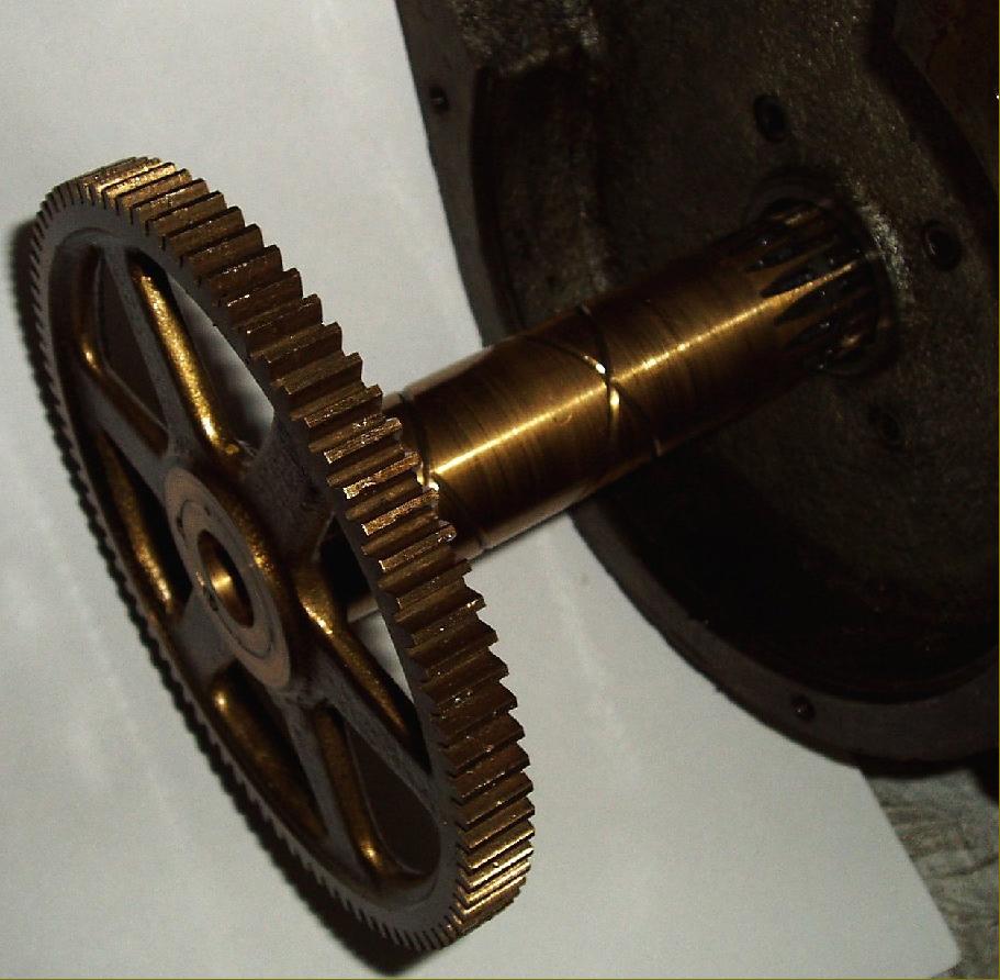
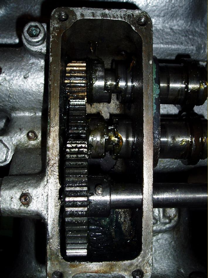
Reduction gearbox case opened showing the fixed-ratio drive and the large bronze gear with the drive shaft from the screwcutting changewheels passing through it.
|
|
|
|
|
|
|
 |
|
|
|
|
|
|
The bronze gear pulled out from its housing. The hollow shaft had a gear formed at its other end (it can just be seen emerging from the casing) used to drive the power sliding and surfacing feeds
|
|
|
|
|
|
|
 |
|
|
|
|
|
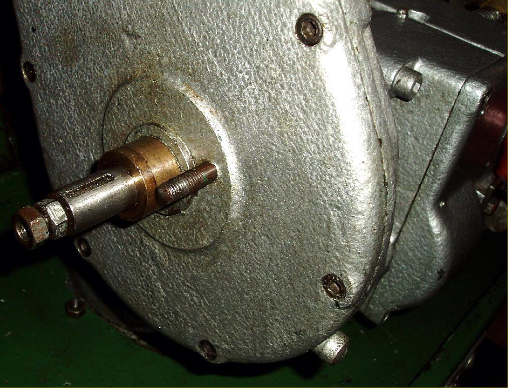
Reduction gearbox cover in place and the shaft to pick up the drive from the screwcutting changewheels protruding through the face
|
|
|
|
|
|
|
|
|
|
|
|
 |
|
|
|
|
|
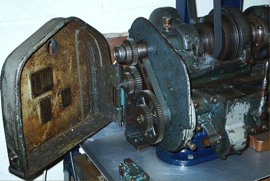
The beautifully-made quadrant arm used to carry the screwcutting changewheels. As no cover was provided, this was left exposed.
|
|
|
|
|
|
|
 |
|
|
|
|
|
|
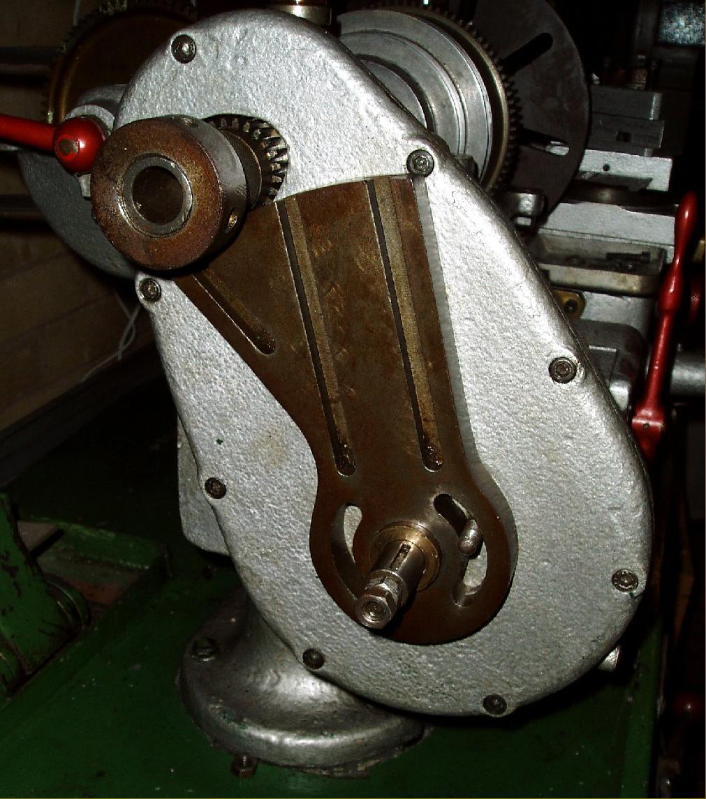
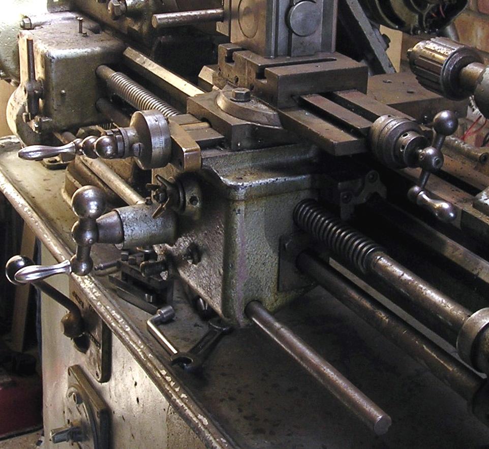
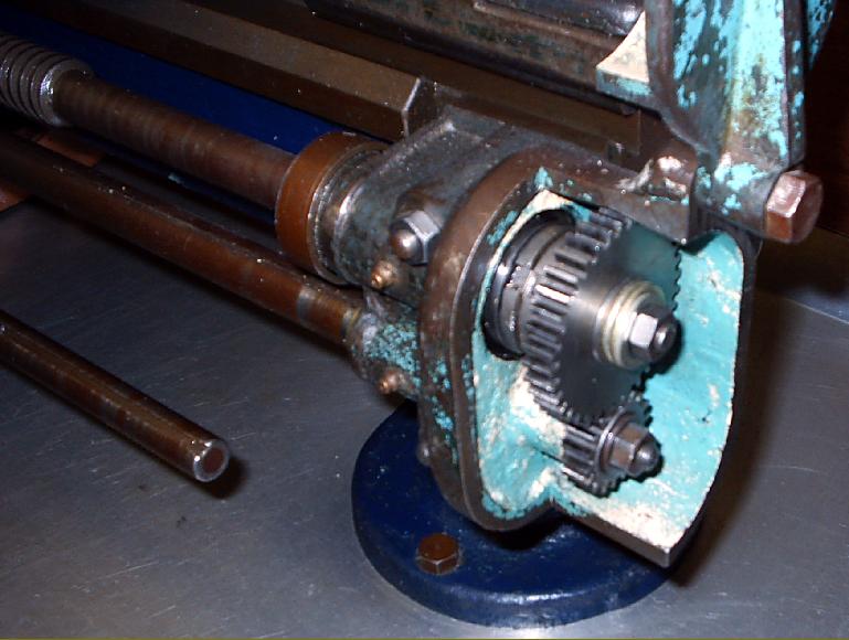
"Selector Gearbox". Here the drive arrived at the top - the bronze gear driven from the Reduction Gearbox and the shaft passing through it from the screwcutting changewheels. The drive passed down to the power-sliding shaft and then to the overhung power cross-feed shaft.
|
|
|
|
|
|
|
 |
|
|
|
|
|
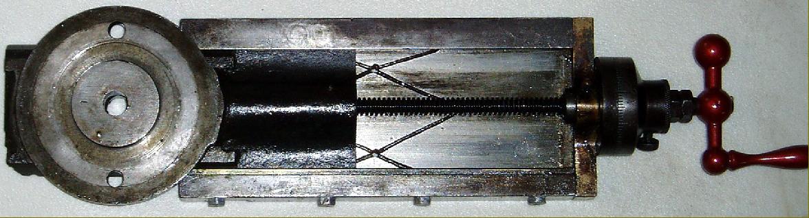
6 gears, arranged in pairs provided, via the leadscrew, 6 rates of sliding feed
|
|
|
|
|
|
|
 |
|
|
|
|
|
|
Pick-off gears (there were six pairs to vary the ratio) transferred the drive from powershaft to leadscrew.
|
|
|
|
|
|
|
|
|
|
|
|
 |
|
|
|
|
|
|
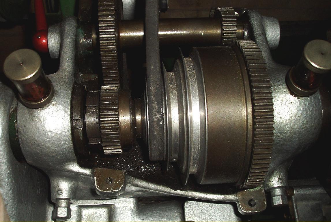
Backgear and 4-step V-belt headstock pulley
|
|
|
|
|
|
|
 |
|
|
|
|
|
|
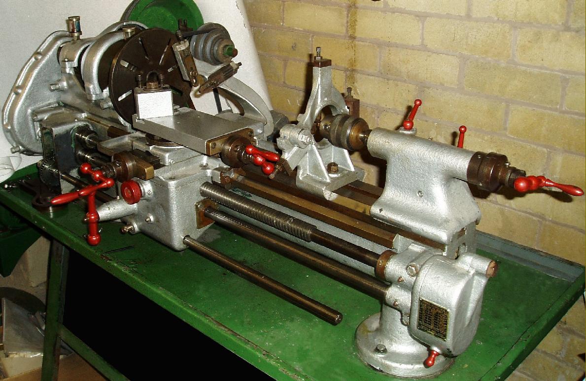
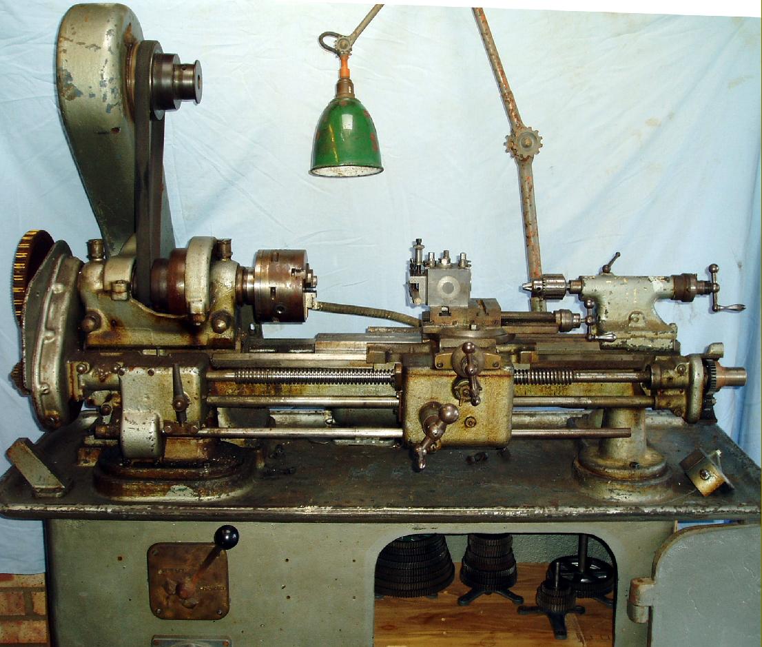
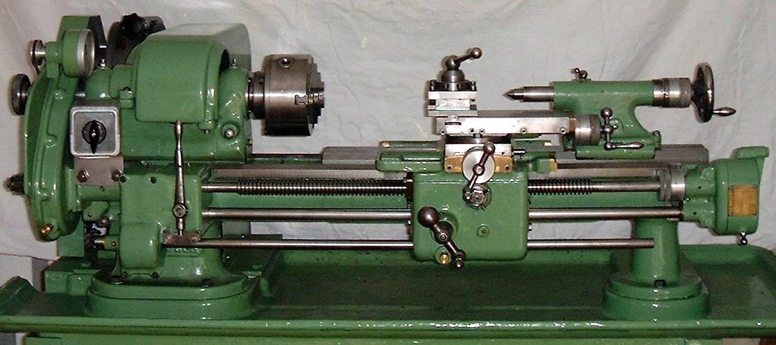
Early Cromwell Mk. 2 mounted on the maker's cast-iron cabinet stand
|
|
|
|
|
|
|
 |
|
|
|
|
|
|
The large diameter, coarse-pitch leadscrew
|
|
|
|
|
|
|
 |
|
|
|
|
|
|
Alternative top slides appear to have been offered-- some machines being found, as shown, with one identical to the type, with exposed slideways and two T-slots, used by Boley on their pre-WW2 Model 3L and 4L lathes. Other lathes had an entirely different arrangement with covered ways and a single T-slot.
|
|
|
|
|
|
|
|
|
|
|
|
 |
|
|
|
|
|
|
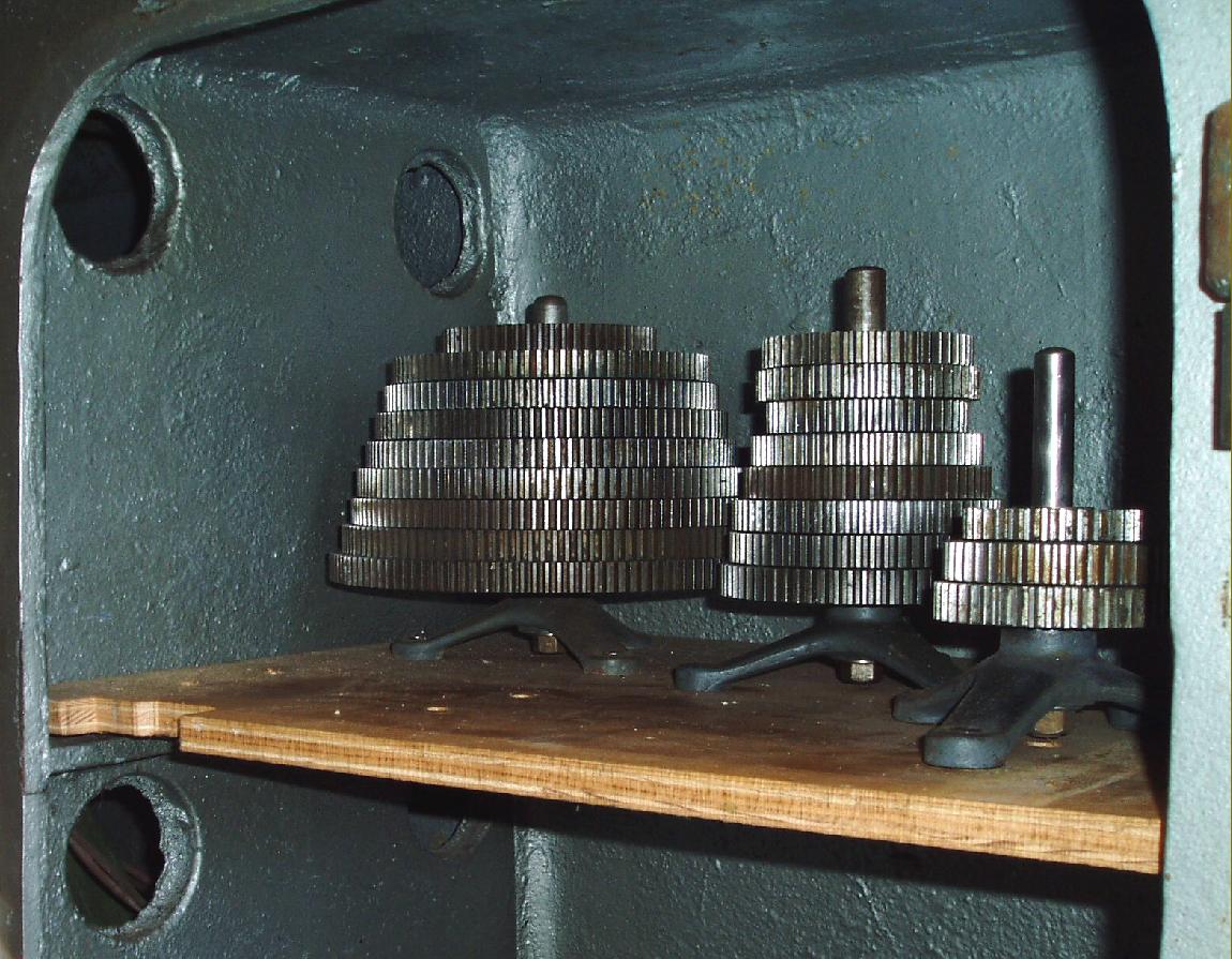
Changewheel and pick-off gear storage was on neat spiders
|
|
|
|
|
|
|
 |
|
|
|
|
|
|
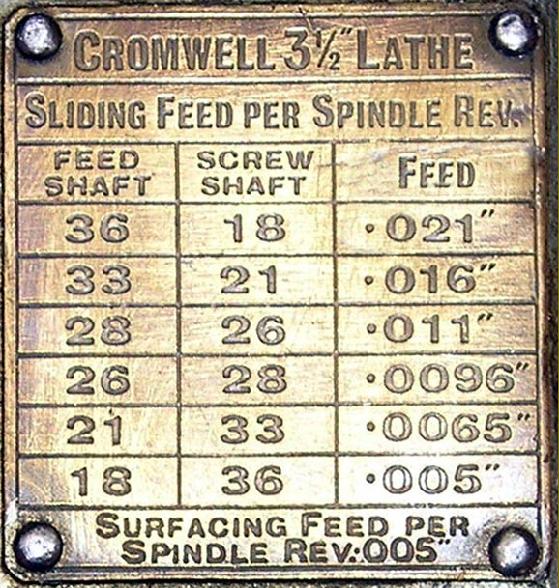
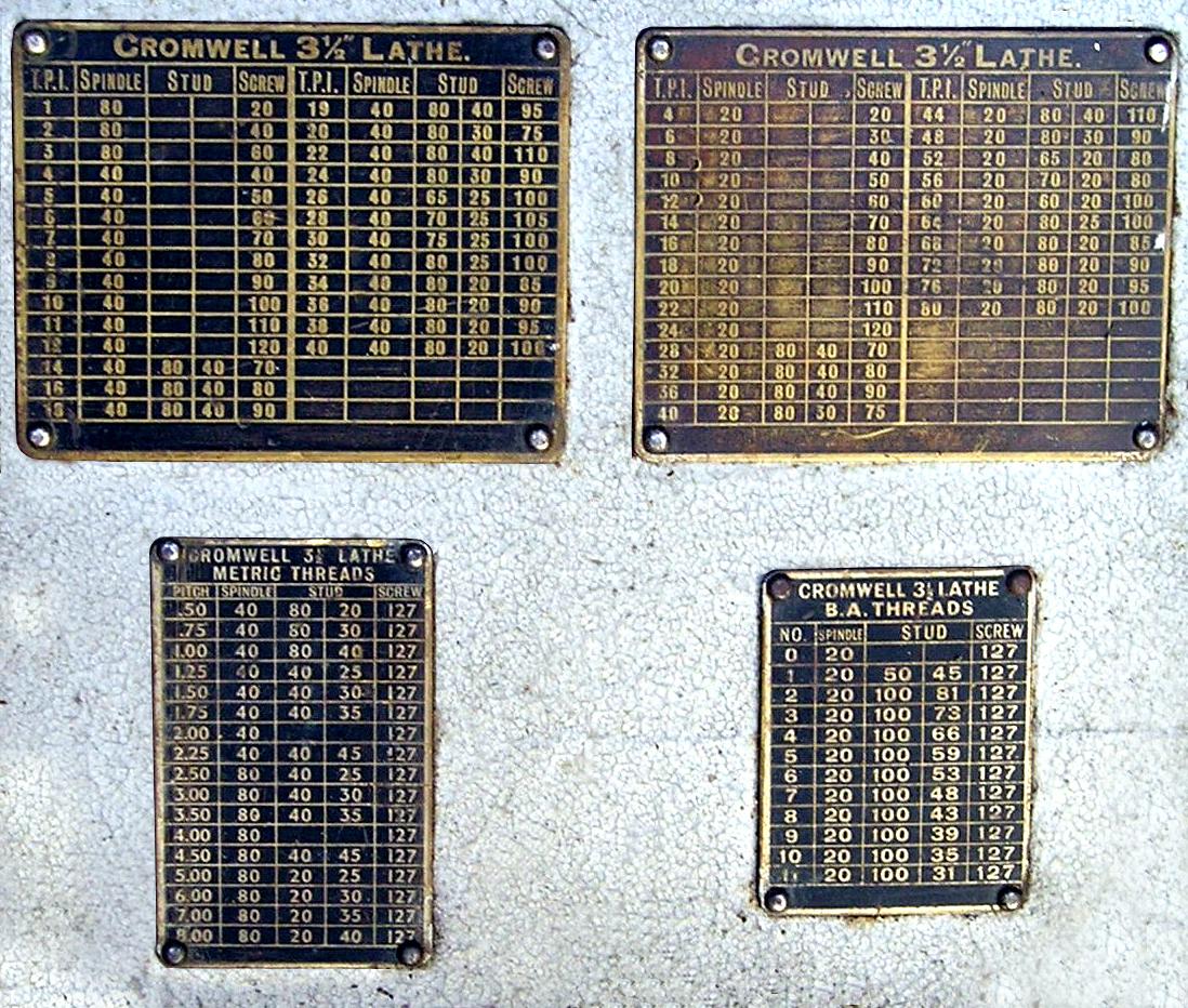
Cromwell Mk. 2 Screwcutting Charts
|
|
|
|
|
|
|
 |
|
|
|
|
|
|
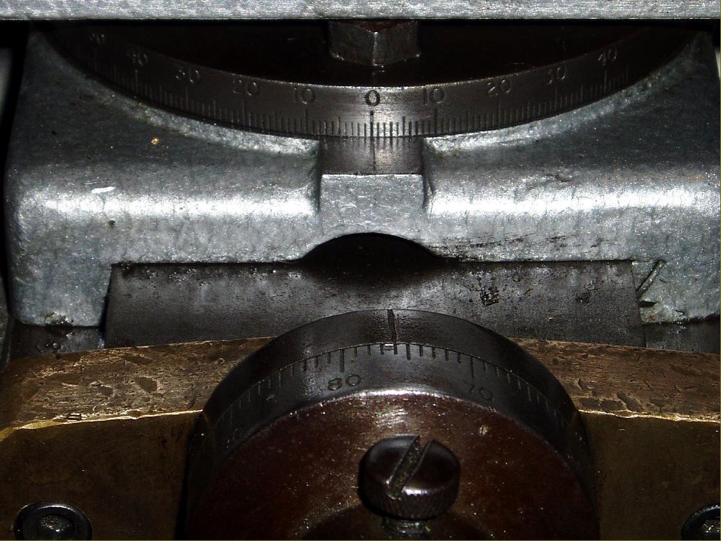
Engraved degree scale for rotating the top slide. On some lathes this casting part was in iron, on others bronze
|
|
|
|
|
|
|
 |
|
|
|
|
|
|
Underside of the top slide. Whilst a normal V-edge was used, with a gib strip, instead of the base casting being flanged for the upper casting to run on this unit was highly unusual in employing the roof of the upper casting instead.
|
|
|
|
|
|
|
|
|
|
|
|
 |
|
|
|
|
|
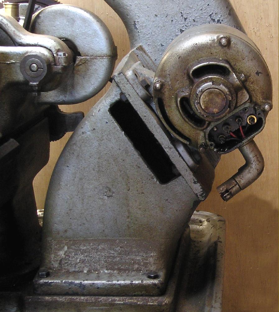
Countershaft motor bracket. The whole of the countershaft drive system was very heavily built.
|
|
|
|
|
|
|
 |
|
|
|
 |
|
|
|
|
|
|
|
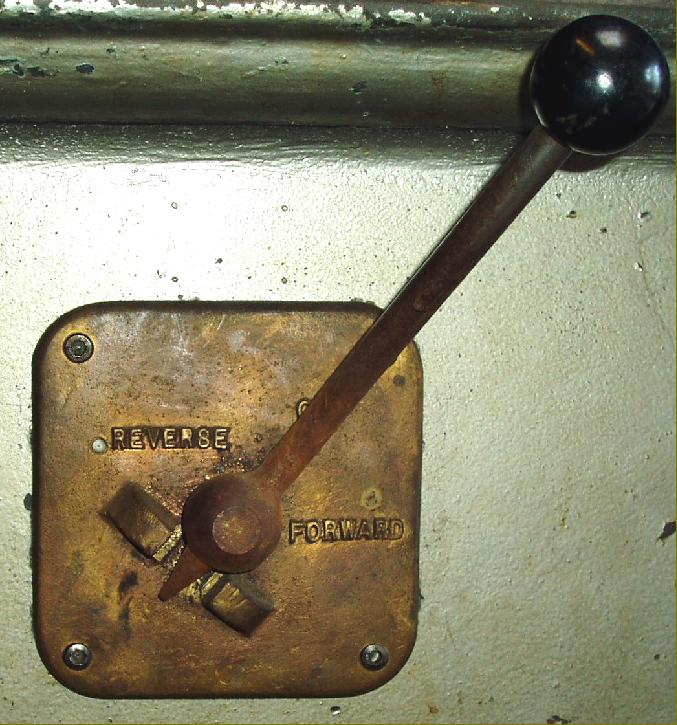
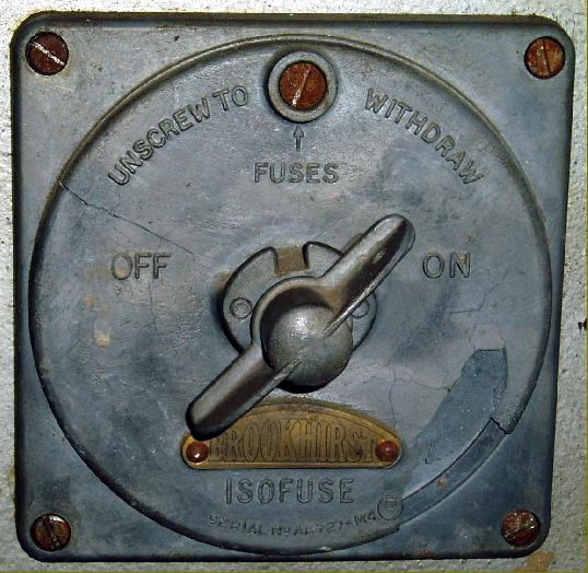
A contrast in fortunes: while the facia used for the reversing switch, above, was over-engineered in cast bronze - an astonishing waste of money - that for the on/off switch - right - appears to have been in ZAMAK.
|
|
|
|
|
|
|
 |
|
|
|
|
 |
|
|
|
|
|
|
|
|
|
 |
|
|
|
|
 |
|
|
|
|
 |
|
|
|
|
 |
|
|
|
|
|
|
|
|
|
|
|