 |
 |
 |
 |
 |
 |
 |
 |
 |
 |
 |
 |
 |
 |
 |
 |
 |
 |
 |
 |
 |
 |
 |
 |
|
|
|
|
|
|
|
|
|
email: tony@lathes.co.uk
Home Machine Tool Archive Machine-tools Sale & Wanted
Machine Tool Manuals Catalogues Belts Books Accessories
Quorn Tool & Cutter Grinder
- modification to allow the sharpening of gear hobs -
Quorn Home Page Quorn Mk. 2 Inspired by the Quorn, the Bornarel
A Manual is available for the Quorn Tool & Cutter Grinder
and a book on tool & cutter grinding
The special, high-quality round drive belts can be supplied.
Either order online here (where you can choose diameters
and lengths), or phone 01298-871633 to discuss any special requirements
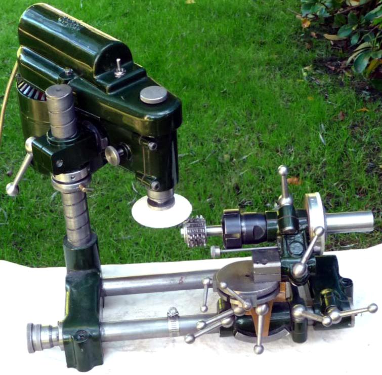
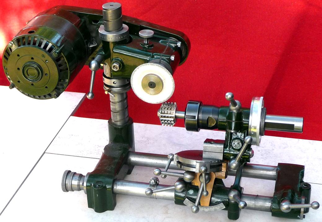
Since this adaptation was made, the owner has realised that there was, in fact, no need to mount the spindle vertically - hobs can be sharpened with the grinding spindle set horizontally as Prof. Chaddock intended (photographs at the bottom of the page illustrate this procedure) However, the threaded collar for fine vertical adjustment is still very useful - and is also shown below.
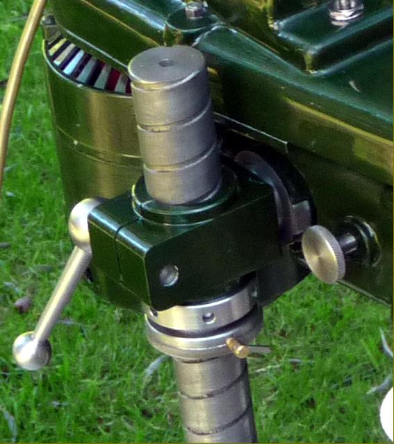
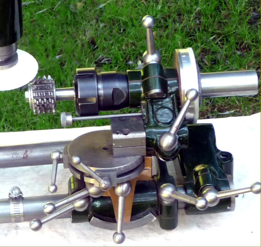
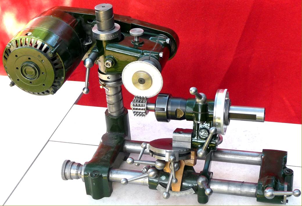
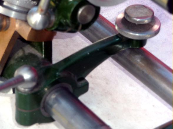
The essence of the original modification was a horizontal shaft that allowed the grinding spindle to be set vertically. The shaft was held a mount slipped over the vertical column with 20 t.p.i threaded collar beneath to allow a fine vertical adjustment. The cut was put on by a rocking-lever adjustment screw that contacted the fixed raiser 1" shaft - which is why the work arbor mount was turned right over. To allow this setting, the adjustment knob on the rotation setting plunger had been taken right back. Note the high-tech carriage stop on the bed rail - a jubilee clip….
|
|
|
|
|
|
|
|
|
|
|
|
|
|
|
|
|
|
|
|
|
|
|
|
|
|
|
|
|
|
|
 |
|
|
|
|
 |
|
|
|
|
|
Head-mounting bracket and, beneath, the threaded collar to allow for fine vertical adjustment
|
|
|
|
|
|
|
 |
|
|
|
|
 |
|
|
|
|
|
|
|
|
|
|
 |
|
|
|
|
|
|
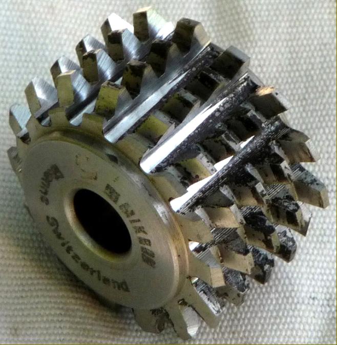
Sharpened hob from a Swiss Mikron gear hobber
|
|
|
|
|
|
|
 |
|
|
|
|
|
|
Since the vertical adaptation was made, the owner has realised that there was, in fact, no need to mount the spindle vertically - hobs can be sharpened with the grinding spindle set horizontally as Prof. Chaddock intended, above.
|
|
|
|
|
|
|
 |
|
|
|
|
|
|
|
|
 |
|
|
|
|
 |
|
|
|
|
|
|
|
|
|
A gear hobbing machine made from a set of castings
available from College Engineering Supply.
The Jacobs Gear Hobbing Machine
This machine, like the Quorn tool and cutter grinder is only available as a set of castings intended for completion in the home workshop. Professional gear hobbing machines are complex and expensive. This machine was conceived by Tom Jacobs who as an engineering apprentice in the 1920's had his interest captured by the hobbing of gears on an industrial scale. Fifty years later he set about designing a fabricated machine more to demonstrate the principles of the process on a home workshop scale than to create a production unit. The machine was capable of producing spur, helical, bevel and worm gears and its making was written up and published in a series of articles in Model Engineer between January and August 1976.
Some years later a set of iron castings was produced by an organisation called Helix which enabled a slightly more robust machine to be made to the same design. These castings are still available today from College Engineering Supply, see http://www.collegeengineering.co.uk/Castings/582.htm . Completed machines can often be seen at model engineering exhibitions. A Jacobs machine set up for cutting spur gears is shown in photo 1. The essence of the machine is a cast iron baseplate supporting a hob spindle in a housing which is driven through a reduction gear and vee belt pulleys by a small motor of ¼ to 1/3 HP. The workpiece is fixed to a spindle whose housing is mounted on the baseplate via three dovetail slides enabling precise movement in all three axes. The workpiece is driven by the hob spindle via a set of index gears, a cardan shaft and worm & wheel such that for spur gears the hob spindle rotates a number of times for one rotation if the workpiece equal to the number of teeth required on the finished gear divided by the number of starts of the hob teeth (usually one). Powered feed is produced by gearing the cross-feed screw to the workpiece spindle (photo 3). The cut is put on with the vertical slide. A useful addition is a differential gear in the index train that allows a gear having a prime number of teeth to be cut without already having one. The index & feed gears specified are 20DP with a 14 ½ degree pressure angle as used for Myford lathe change wheels and therefore generally available in a variety of tooth numbers.
The use of a cardan shaft using two universal joints to transmit the index drive is a compromise since the input and output shafts will not be quite parallel but inclined at an angle equal to the helix angle of the hob when making spur gears. This means that the workpiece movement is not quite at constant velocity. However since the helix angle of spur gear hobs is generally no greater than 30, this error is small and acceptable for most model engineering work.
With straightforward modifications the machine can make helical gears though the index ratio must be subtly altered according to the helix angle, the feed rate and PCD of the gear and an additional gear train is used in this example. Also a bevel drive or some other means is necessary to keep the input and output of the cardan shaft parallel. Worm wheels can be produced using powered vertical (plunge) feed. Worm wheels can also be made using ACME taps as hobs by effecting tangential feed by powering the longitudinal slide via a bevel drive and a further cardan shaft. Again, the index ratio must be modified to correct for this feed parallel to the hob axis.
The size of gear which can be produced is limited by the rigidity of the machine to about 20DP or Mod 1.25. Gear diameters of up to 6" can be accommodated. Gears at the limit of this range in steel need up to 5 passes so the process is steady. Limit switches can be fitted to the cross slide so that the machine can left to run unattended.
More on the Jacobs here
|
|
|
|
|
|
|
|
|
|
|
|
|
|
|
|
|


