 |
|
|
|
|
|
|
|
|
|
|
|
|
|
|
|
|
|
|
|
|
|
|
|
|
|
|
|
|
|
|
|
|
|
|
|
|
|
|
|
|
|
|
|
|
|
|
|
|
|
|
|
|
|
|
|
|
|
|
|
|
|
|
|
|
|
|
|
|
|
|
|
|
|
|
|
|
|
|
|
|
|
|
|
|
|
|
|
|
|
E-Mail Tony@lathes.co.uk
Home Machine Tool Archive Machine Tools For Sale & Wanted
Machine Tool Manuals Machine Tool Catalogues Belts Accessories
Porter-Cable Lathes
& W.C.Lipe Production lathes
Toolroom and Conventional Porter-Cable Lathes Milling Attachment
Founded in 1906 by R. E. Porter, G. G. Porter and F. E. Cable as a jobbing machine shop in Syracuse, N.Y., Porter Cable are still active today, selling a range of hand tools, wood lathes and associated products. In 1960 they joined forces with another tool Company, Delta, though the products still retained their separate brand identities.
Having begun by building conventional engine, toolroom and production lathes, during the 1920s Porter-cable turned their attention (most successfully) to hand and power-tool manufacturer - though the lathes did continue, albeit in the form of production machines only, until 1930s. Their entire output appears to have been directed at industry, with no attempt to sell machines into the amateur or repair workshop markets; as a result, as the conventional engine lathes were probably made for less than ten years (and the production types, once obsolete, mostly scrapped), they are now rare. In addition to the lathes, in early years a shaper was also manufactures (a design taken over by Logan and sold as their own) and a milling attachment.
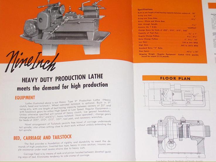
As far as is known, three production lathes were made, each intended for repetition use on short jobs: The first, dating from 1914 (Patent 1196024 dated 1915/16), had no model designation but was described as the Rapid Production Lathe while the second, introduced in the 1930s, was a heavily revised version of the first and listed as the Carbo-Lathe (it's shown towards the bottom of the page). A third type, hydraulically driven, was developed during the late 1930s and known as the Carbo-Matic. In later years matters became a little more complicated with the well-known firm of William C. Lipe - who, from 1929, became W.C. Lipe Inc., Syracuse, NY. (Production Tools, Special Machines). In 1937 Lipe bought the "Lathe Division" of Porter-Cable who, at the time, were making just the early 9-inch Rapid Production, the Carbo-Lathe and Carbo-Matic. The lathe must have been relatively popular for, in 1940, Lipe announced an extension to their Syracuse-based Machine Tool Division to provide for increased production of the Carbo. Sales brochures for the range extended into the late 1940s and showed the original, unchanged 9-inch still in production as two models: the Heavy-Duty Production with two speed ranges (that spanned 139 to 841 r.p.m. and 365 to 2072 r.p.m.) and a High-Speed Production with a single speed range of 700 to 3600 r.p.m. Also offered in their established forms were the Carbo-Lathe (now described as "Semi-Automatic") and the Carbo-Matic Fully Automatic.
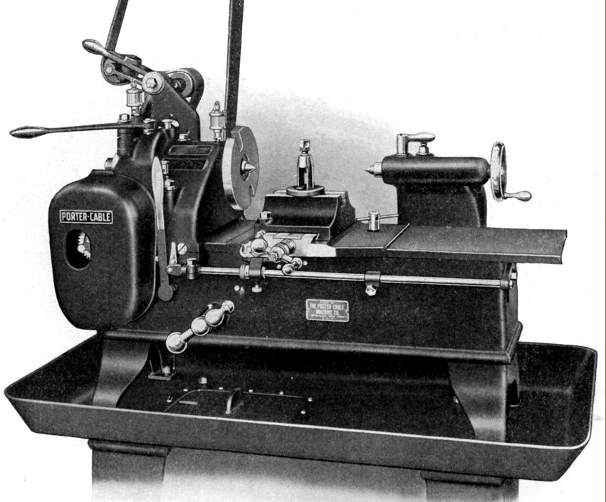
Compact and strongly built (it occupied a space just 421/2" x 211/2" and weighed around 1000 lbs) the original Rapid Production had a 9-inch swing and could take either 14 or 20 inches between centers. In essence this was just a robust, plain-turning lathe without screwcutting but with power feed along the bed. It was intended, according to the makers, to be a low-cost machine for the manufacture of shorter parts and arranged so that it would survive hard use in the hands of unskilled operators.
Although the concept of a simple lathe for simple jobs was not unusual, the manner of its execution was, with almost every part of the machine different to usual practice. Drive to the 1-inch bore spindle (running in massive tapered bronze bearings and lubricated by drip-feed oilers) came from a quickly changed pulley, mounted at the rear of the headstock, that was intended to be driven from either overhead line shafting or from an optional, built-on motor unit with switchgear. The input shaft, which ran from the back face of the headstock to the front, passed beneath the spindle and drove it through worm-and-wheel gearing. At the front, the shaft carried a gear that meshed with a train to take the drive down to a second shaft, parallel to the first, also fitted with worm-and-wheel gearing that drove a shaft that passed down the centre line of the bed. At the headstock end of the shaft was a multi-tooth dog clutch operated by an external lever and also connected, via a linkage, to an adjustable knock-off bar arranged along the front face of the bed. With the spindle running at 1000 r.p.m. the use of low-ratio worm-and wheel gearing meant that the centre-line shaft was turning at just 100 r.p.m. (See the patent drawings below for a full understanding of how this was arranged).
In keeping with its other novel features, the carriage drive was also unconventional. The shaft that passed down the centre line of the bed ended half-way along where it drove, using bevel gears, a vertical shaft. At the top of the vertical shaft was a gear that engaged with a rack formed as part of the saddle. Instead of being guided by the usual inverted V and flat ways - or along V-edges - the centre of the saddle was formed with a male dovetail section that ran in female ways machined down the centre line of the bed.
For manual drive of the carriage a handwheel was positioned on the front face of the bed and connected to the powershaft by bevel gears. Thus, the entire drive was by gears of one sort or another (no screw threads being used), and obviously designed for heavy use and a long, trouble-free life.
On later models, instead of drip-feed oilers, an oil bath was used to lubricate the headstock internals with a simple oil slinger, fastened to the input (clutch) shaft, distributing the lubricant to the worm, worm wheel and spindle bearings.
With the massive tailstock carried on the bed's rear face on separate, widely-spaced angle-edge ways, the flat-topped bed was left clear for its full length and able to be completely covered by long, telescoping covers to both left and right of the cross slide (that on the left sliding beneath the headstock casting) an essential requirement to prevent wear on a machine in continuous, heavy-duty use. As a bonus, the entire carriage could be slid off the end of the bed for maintenance or replacement by one of another kind for special jobs.
As part of the regular equipment, just a single cross slide was fitted - though both a proper compound rest was available and a slide with a type of built-in taper turning. Toolposts were simple but rugged and included a typically American style of rocker post, a clog-heel open type and a full-length "gang" holder that could be set up with multiple tools.
Accessories included a number of useful items including: a rear-mounted, facing (cut-off) slide (Patent 1385491) driven by a cam that could be adjusted over a range of 2 inches and with 2 inches of slide travel; an angular facing attachment - similar to the standard unit but with the cross slide able to be swivelled through an arc of 180°; a taper-turning attachment; collets with closure by either an ordinary screw wheel or quick-action lever.
If any reader has a Porter-Cable lathe of this type the writer would be interested to hear from you..
|
|
|
|
|
|
|
|
|
|
|
|
|
|
|
|
|
|
|
|
|
|
|
|
|
|
|
|
|
|
|
|
|
|
|
|
|
|
|
|
|
|
|
|
|
|
|
|
|
|
|
|
|
|
|
|
|
|
|
|
|
|
|
|
|
|
|
|
|
|
|
|
|
|
|
|
|
|
|
|
|
|
 |
|
|
|
|
|
|
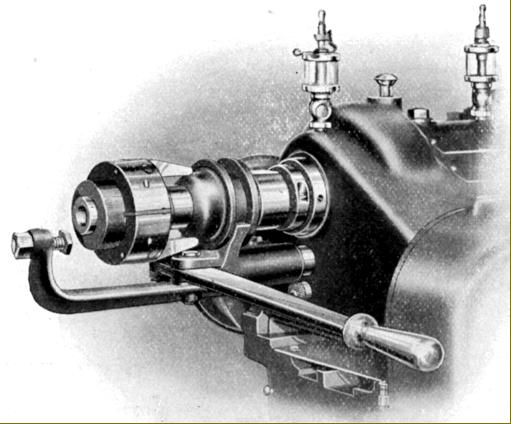
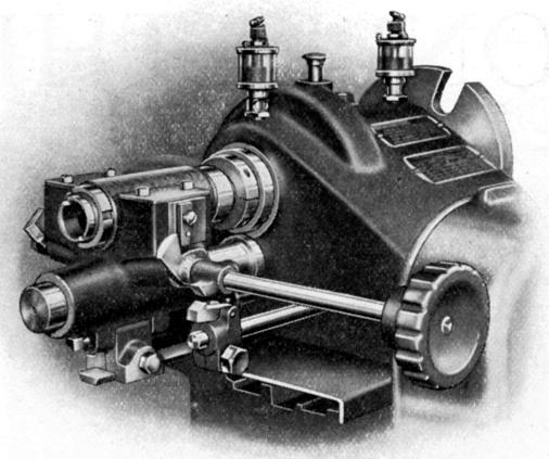
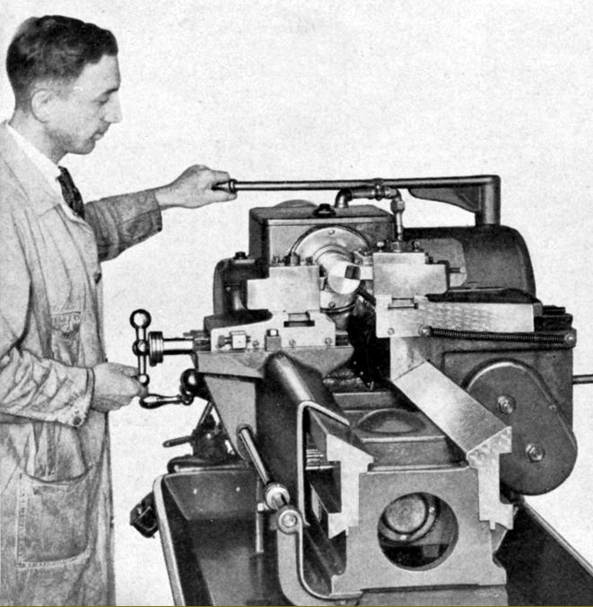
Porter-Cable Rapid Production Lathe circa 1914/19 with drive from a factory line-shaft
|
|
|
|
|
|
|
 |
|
|
|
|
|
|
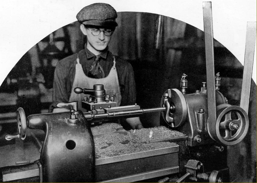
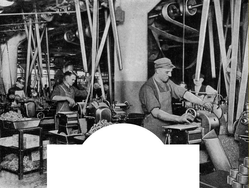
Four tools being used at once to grove and chamfered a 3.5% nickel steel n armature shaft. As no longitudinal movement was required an extra-long tool holder was fitted with just in in-and-out movement to complete the job at the rate of 30 per hour.
|
|
|
|
|
|
|
 |
|
|
|
|
|
|
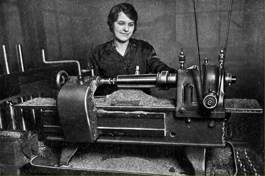
A bronze hub liner for a 56" artillery wheel being turned on an expansion arbor. If the girl operator really was a shop-floor worker (though judging by her bead necklace, had been drafted in from the office to add a touch of glamour), it's unlikely that her benign smile would have lasted - the work rate for this piece being 300 per hour.
|
|
|
|
|
|
|
 |
|
|
|
|
|
|
Automobile transmission gear blank. The four diameters were turned to plus or minus 0.001" with 30 completed every hour
|
|
|
|
|
|
|
 |
|
|
|
|
|
|
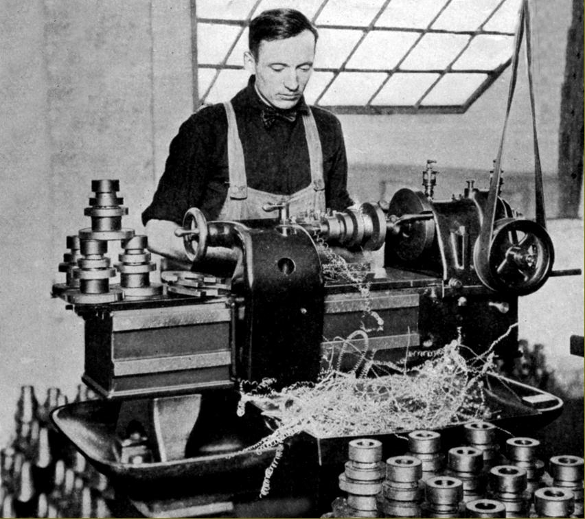
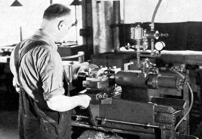
The factory of the Stewart-Warner Speedometer Corporation in Chicago. The main job was to machine bars of malleable iron with a turned section 9/16" in diameter and 21/2" long. In an Eight-and-a-half hour day each lathe could produce 925 pieces
|
|
|
|
|
|
|
 |
|
|
|
|
|
|
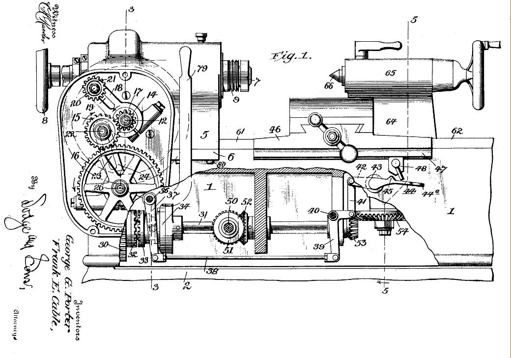
Section though the 1915 patent drawing showing the various drive arrangements. Parts 32 and 33 are the clutch for the horizontal drive shaft; parts 50, 51 and 52 are the bevel gears and shaft for hand movement of the carriage; parts 53 and 54 are the bevel gears that take the drive vertically to a rack-and-pinion drive that moves the carriage along the bed.
|
|
|
|
|
|
|
 |
|
|
|
|
|
|
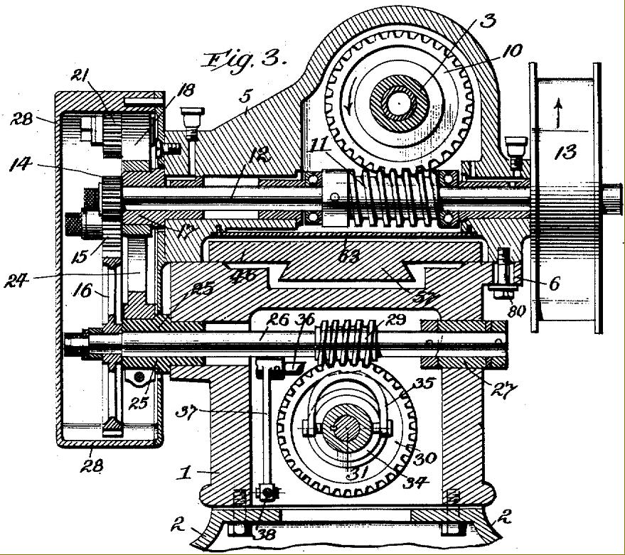
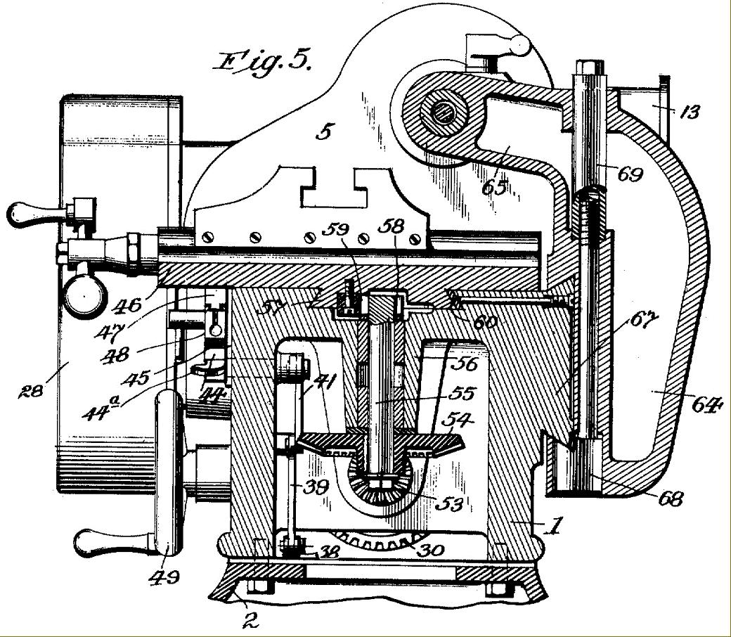
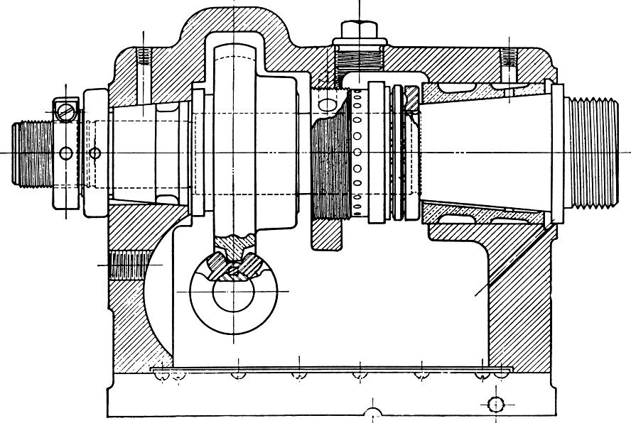
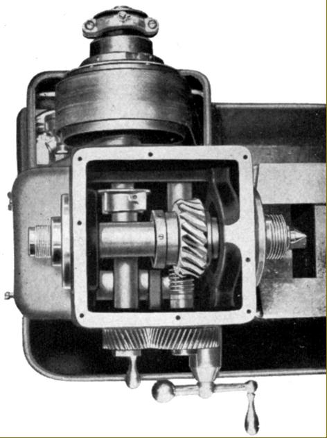
Section across the headstock and bed showing the input pulley (13) and upper transverse shaft (12) driving the headstock spindle (3) through worm-and wheel gearing 10 and 11). The lower transverse shaft (26) was also fitted with worm-and wheel gears (29 and 30) that turned a shaft running along the centre line of the bed to eventually drive the carriage.
|
|
|
|
|
|
|
 |
|
|
|
|
 |
|
|
|
|
|
|
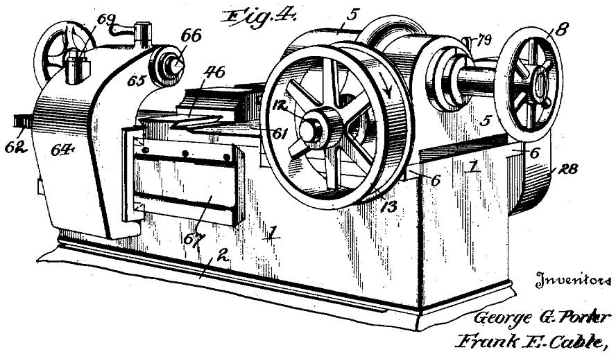
Section showing the vertical drive (55) to the rack-driven carriage and the tailstock 64) and its ways (67)
|
|
|
|
|
|
|
 |
|
 |
|
|
|
|
|
|
|
|
|
|
Lever-action collet closer
|
|
|
|
|
|
|
|
 |
|
|
|
 |
|
|
|
|
|
|
Carriage quick-return attachment - powered by gravity
|
|
|
|
|
|
|
|
 |
|
|
|
|
|
|
|
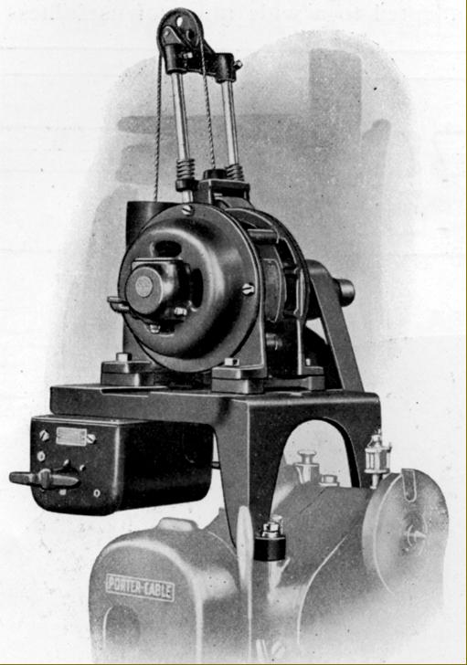
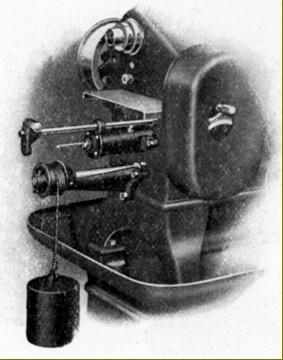
Motor and switchgear attachment with a counterweight to tension the 2-inch wide drive belt
|
|
|
|
|
|
|
|
|
|
|
|
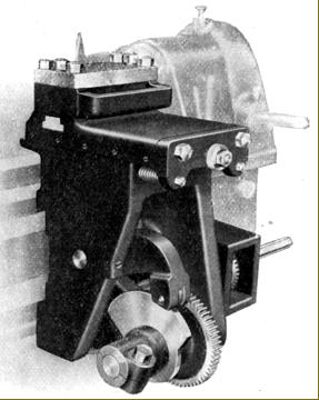
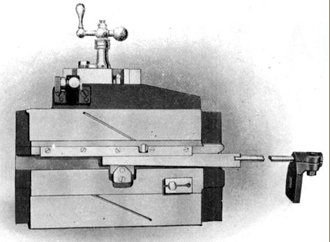
Power cross feed (facing) attachment
|
|
|
|
|
|
|
|
|
|
 |
|
|
|
 |
|
|
|
|
|
|
|
|
|
|
|
|
|
|
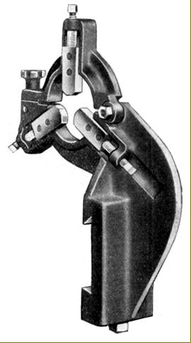
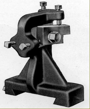
Fixed steady for mounting on the tailstock ways at the back of the bed
|
|
|
|
|
|
|
 |
|
|
|
 |
|
|
|
|
|
|
|
|
Open slide tool holder with rocker base
|
|
|
|
|
|
|
|
|
|
|
 |
|
|
 |
|
|
|
|
|
|
|
Gang tool holder closed type
|
|
|
|
|
|
|
Gang tool holder open type
|
|
|
|
|
|
|
|
|
|
|
 |
|
|
|
|
|
|
|
|
|
|
 |
|
|
|
|
|
|
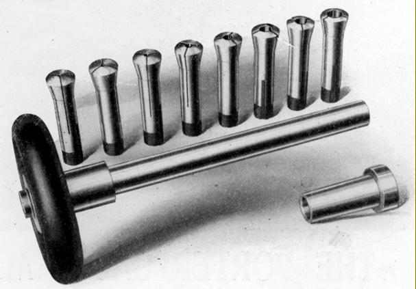
Standard wheel-operated collet set with nose-piece adapter
|
|
|
|
|
|
|
 |
|
|
|
|
|
|
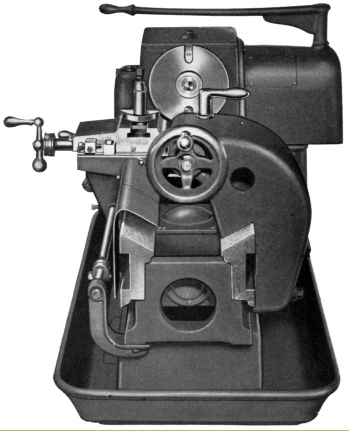
Section through the headstock of a late model plain-bearing 9-inch Rapid Production Lathe
|
|
|
|
|
|
|
|
|
Porter-Cable Carbo-Lathe
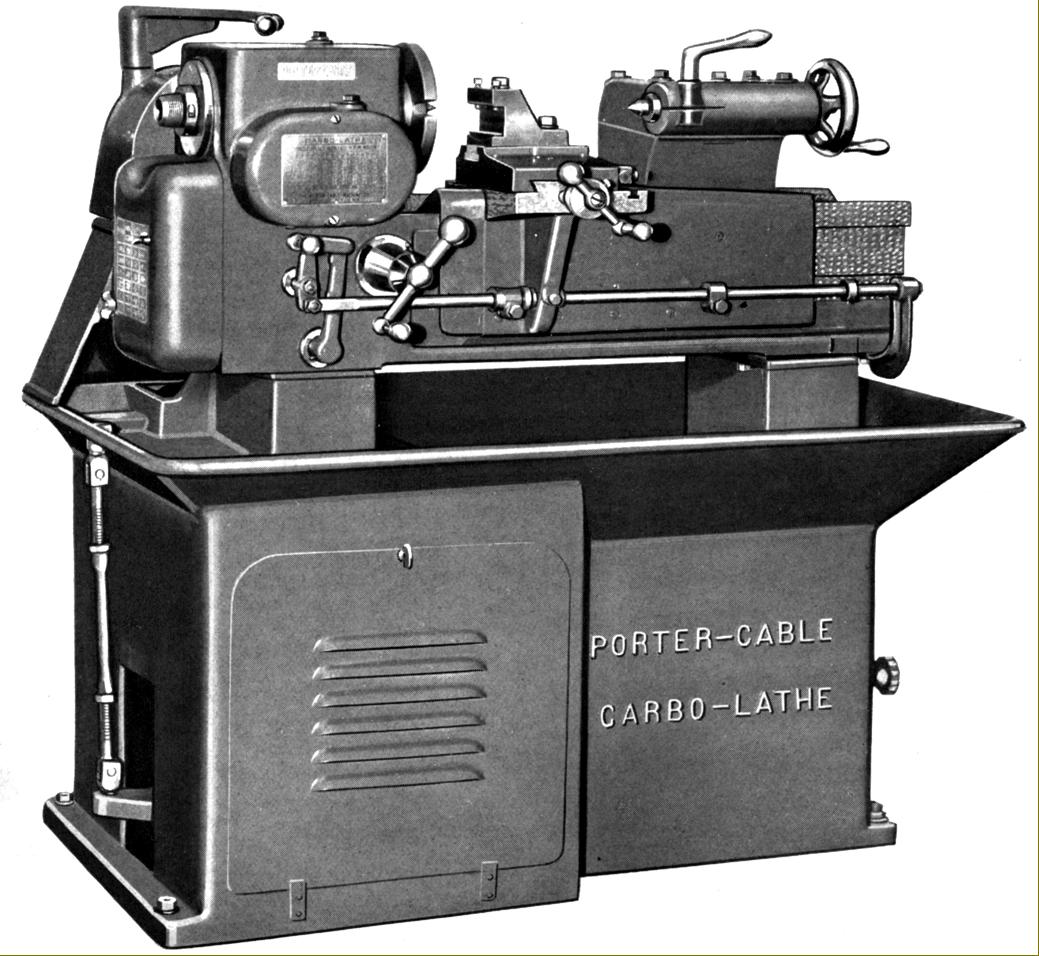
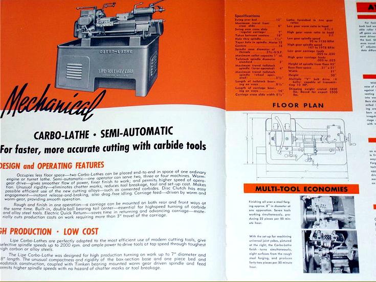
Believed to have been introduced in 1932 - eighteen years after production started of their original High-speed Production Lathe - the 7" x 18" Carbo-lathe was Porter-Cable's answer to the need for greater capacity, higher speeds, increased rates of metal removal and an up-to-date, built-in drive system. Its name, "Carbo", referred to the machine's ability to make use of the recently introduced carbide-tipped tooling, a development that allowed significant improvements to be made in turning performance
Because the original machine was still available, the new model was described in some of the Company's literature as the Super Carbo-Lathe and, although it had the same layout and bore a close resemblance to the earlier version and worked in the same way, it was enormously strengthened and altered in many ways - with a quite different design of bed and the weight almost doubled to 2000 lbs. To reduce friction losses in the transmission a total of 18 roller or ball races was used throughout the lathe. Like its predecessor it was, in comparison to a full-blown capstan or turret lathe, an uncomplicated and relatively inexpensive machine, intended for a niche market and designed to machine simple jobs that would be produced non-stop for several months - though more complex tasks could be broken down into stages with several machines, installed alongside each other, tooled to perform one operation after another.
Made from a chrome-nickel iron, the bed and headstock were cast as one, weighed 600 lbs and carried mirror-image ways at the top and on the front and back faces of the bed. The top ways sloped steeply inwards (in a V-formation giving some extra clearance beneath the spindle line) with a vertical outside surface and below, separated by a sunken rectangular section, a second pair of V-ways to guide the lower edge of the carriage. As before, the rear slide carried the tailstock with that at the front responsible for the carriage (the latter arrangement resembling the design used by Rivett on the 8-inch Precision and 608 toolroom lathes).
With a bore of 17/16", a massive No. 5 Morse taper socket (sleeved down to 3 Morse) and a 2.75" x 6 t.p.i. thread, the 0.5 nickel chrome steel spindle ran in Timken taper roller bearings and was powered by a motor of up to 10 h.p. AC, or 7.5 h.p. DC, held on an adjustable plate in the left-hand compartment of the cast-iron stand. Four V-belts took the drive up the rear of the machine - an externally mounted turnbuckle being used to set the belt tension - with, at the top, a disc clutch connected to a transverse shaft that passed beneath the spindle and then, via a pair of 1.75-inch wide pick-off gears (under a cover on the headstock's front face), to a second shaft, parallel to the first that turned the spindle through worm-and-wheel gearing. A choice of two ratios was offered: a lower of 3.5 : 1 that gave spindle speeds from 95 to 1130 r.p.m. and a higher of 2:1 that provided 170 to 2000 r.p.m. An oil bath was used to lubricate the headstock internals with a simple oil slinger, fastened to the input (clutch) shaft, distributing the lubricant to the worm, worm wheel and spindle bearings.
Carriage feeds were provided (cheaply but rather inconveniently) by three pick-off gears under a cover at the headstock end of the lathe - the rates of travel per revolution of the spindle being 0.005", 0.01", 0.015", 0.02", 0.025" and 0.03". The feed gearing from the headstock was arranged so that the drive was taken by worm-and-wheel gearing from the lover headstock cross shaft, this reduction allowing the first pick-off gear to rotate at 100 r.p.m. when the spindle was turning at 1000 r.p.m. The lowest pick-off gear turned a clutched shaft (with handwheel attachment) that extended the length of the bed and drove an enclosed, oil-bath lubricated, 10 : 1 ratio worm-and-wheel gear assembly bolted to the inside face of the carriage. The worm wheel (the larger gear) was connected to vertical shaft that carried on its upper end a pinion gear that engaged a rack fastened to the inside of the saddle. Along the front of the bed was a bar, arranged to provide a pre-set disengage to the power feed with a linkage connecting it to the dog clutch fitted to the powershaft at its headstock end.
Equipped with a 1.75-inch diameter, No. 3 Morse taper barrel having 4 inches of travel under lever control and 3.5 inches by screw feed, the tailstock was very heavily built with 8.5" of bearing surface against the bed.
A number of standard accessories were offered including: a rear-mounted, 8-inch wide facing (cut-off) slide that could be adjusted over a range of 2 inches and with 2 inches of slide travel; an angular facing attachment - similar to the standard unit but with the cross slide able to be swivelled through an arc of 180°; a taper-turning attachment; a special, extra heavy-duty tailstock with a built-in ball-bearing centre and available with screw, lever or pneumatic operation; collets with closure by either an ordinary screw wheel or quick-action lever and a number of different toolposts in including an American style of rocker post, a clog-heel open type, a full-length "gang" holder that could be set up with multiple tools and an ordinary 4-way type.
At some point in the mid 1930s Porter-Cable introduced a hydraulically driven Carbo lathe but, as no details are currently available, it is pure assumption to conclude that the expensive worm-and-wheel gearbox and rack drive to the saddle was replaced by a cheap hydraulic cylinder.
Having sold their Lathe Division in 1937 to W.C.Lipe, Porter cable concentrated their efforts on the power-tool market..
|
|
|
|
|
|
|
 |
|
|
|
|
|
|
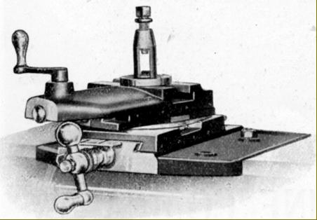
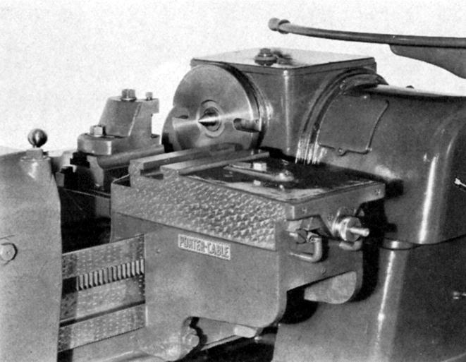
Porter-Cable "Carbo-Lathe" as sold during 1932/33
|
|
|
|
|
|
|
 |
|
|
|
|
Made from a chrome-nickel iron, the bed and headstock were cast as one, weighed 600 lbs and carried mirror-image ways at the top and on the front and back faces of the bed. The top ways sloped steeply inwards (in a V-formation giving some extra clearance beneath the spindle line) with a vertical outside surface and below, separated by a sunken rectangular section, a second pair of V-ways to guide the lower edge of the carriage. As before, the rear slide carried the tailstock with that at the front responsible for the carriage (the latter arrangement resembling the design used by Rivett on the 8-inch Precision and 608 toolroom lathes).
|
|
|
|
|
|
|
|
|
 |
|
|
|
|
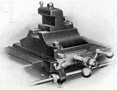
Four V-belts took the drive up the rear of the machine - an externally mounted turnbuckle being used to set the belt tension - with, at the top, a disc clutch connected to a transverse shaft that passed beneath the spindle and then, via a pair of 1.75-inch wide pick-off gears (under a cover on the headstock's front face), to a second shaft, parallel to the first that turned the spindle through worm-and-wheel gearing.
|
|
|
|
|
|
|
|
|
 |
|
|
|
|
 |
|
|
|
|
 |
|
|
|
|
 |
|
|
|
|
 |
|
|
|
|
|
|
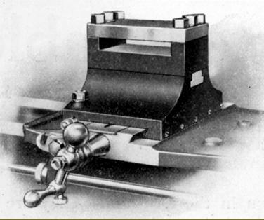
Carbo-lathe facing attachment
|
|
|
|
|
|
|
|
|
|
 |
|
|
|
|
|
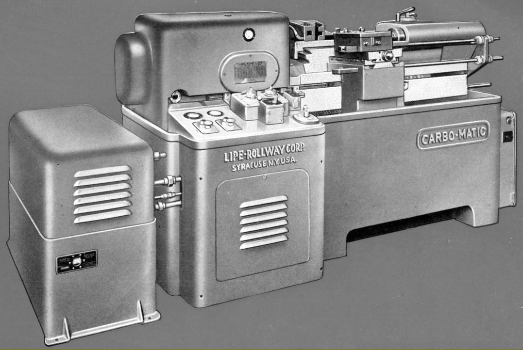
Hydraulic Carbo-Matic as made from the late 1930s into the 1940s
Built along very similar lines to the earlier models but of massive construction (around 8000 lbs) and greater capacity, the Carbo-Matic took 30" between centres and had a swing over the bed of 15".
A full automatic cycle was available, including one for tool relief. From its centre position the front carriage (moved by a hydraulic cylinder acting through rack-and-pinion gearing) could be moved through 15.5" left or right and was fitted with a double cross slide that allowed straight, taper and (with the right tools) form turning. Facing cuts of up to 10" in diameter could be tackled. Automatic stops were fitted to all feeds and allowed a job to be set up precisely and without the operator having to make any decisions.
Hardened and ground, the 19/16" bore headstock spindle had an American Standard spindle nose and retained the well-proven worm-gear drive. It ran in either Timken taper-roller bearings or special ball races with the complete spindle assembly, gears and bearings fitted in a separate cartridge and mounted as a unit within the headstock. A pressure pump supplied lubricant to with an independent supply arranged for the bed and slides - where the oil was directed from the centre to the outside of the ways to flush out debris.
The usual slow-to-change but reliable pick-off gears provided two ranges of spindle speeds (62 to 1046 r.p.m. and 600 to 3600 r.p.m.) with six V-belts transmitting the drive from a motor that could be as powerful as 20 h.p. A separate hydraulic power pack was provided with high and low pressure pumps mounted on a 40-gallon tank and driven from a shared h.p. motor.
Automatic starting and stopping of the spindle and coolant pump was arranged through interconnection of hydraulic and electrical controls and, for further automation, the spindle could be fitted with a hydraulically chuck and collet closers.
Careful consideration had been given to routine maintenance and daily chores with the large chip pan able to be cleaned through a chute in the rear without stopping the machine or disturbing the operator. Hydraulic control units could be removed individually without disturbing pipework so minimising any loss of production time.
|
|
|
|
|
|
|
 |
|
 |
|
|
|
|
|
|
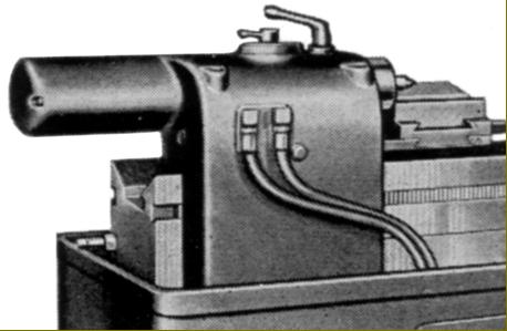
Hydraulic Carbo-Matic tailstock with hydraulically-operated spindle
|
|
|
|
|
|
|
|
|
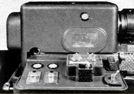
Hydraulic Carbo-Matic headstock-mounted control panel
|
|
|
|
|
|
|
|
|
|
 |
|
|
|
|
|
|
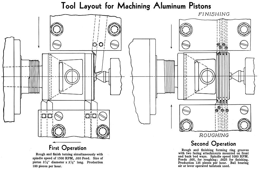
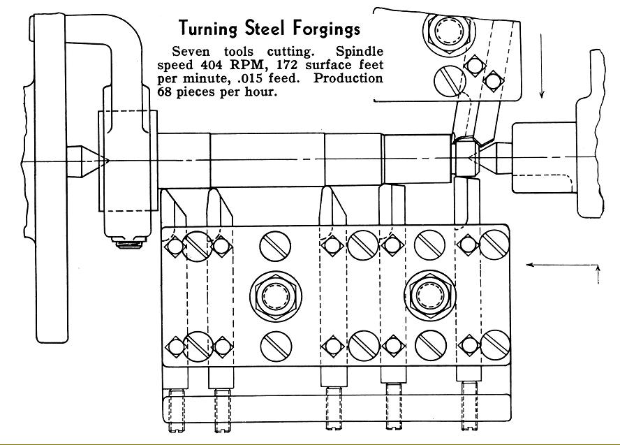
Above and below: suggested typical tool layouts
|
|
|
|
|
|
|
 |
|
|
|
|
 |
|
|
|
|
|
|
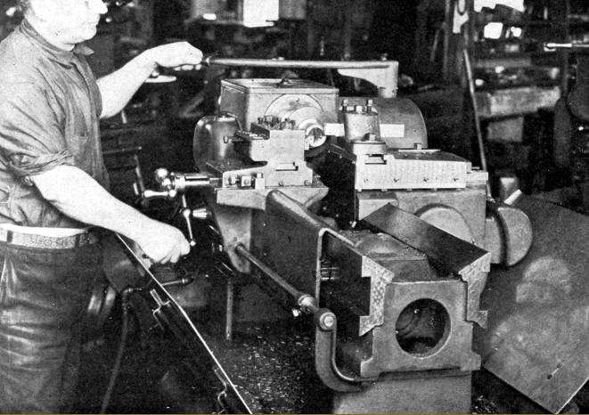
Early 1940s and the Carbo-Lathe continues in production in several forms
|
|
|
|
|
|
|
 |
|
|
|
|
|
 |
|