|
Home Machine Tool Archive Machine-tools for Sale & Wanted Jones & Shipman 540 |
||
|
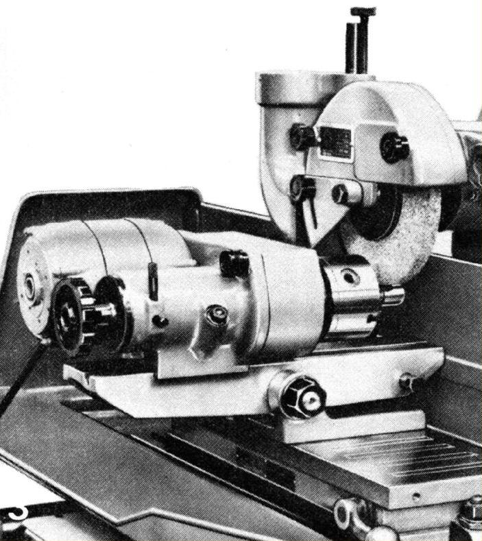
Precision Circular Grinding Attachment: this consisted of a baseplate mounted centrally on a tilting sine platform. Three speeds were available from the self-contained motor and drive assembly with the workhead accepting collets, a 3-jaw chuck or a No. 1 Morse taper centre. The maximum swing was 4.5 inches (114 mm) |
||
|
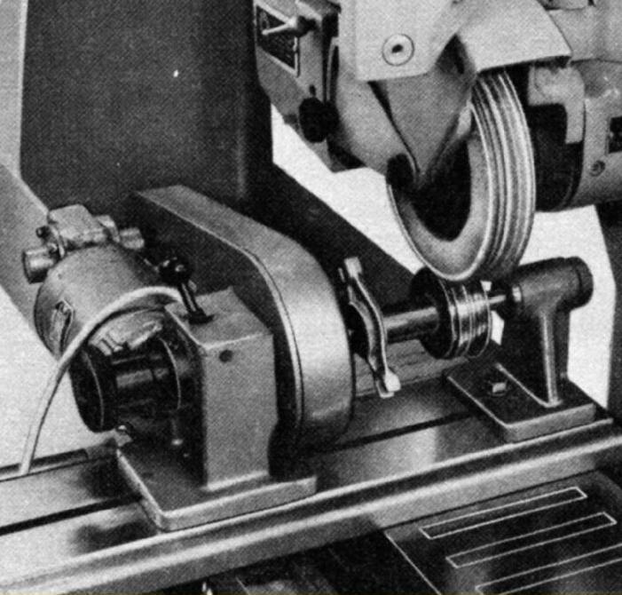
"Mayform" Cylindrical Grinding Attachment. This had a 3-speed live and dead spindle workhead with spring-loaded centres and with a length capacity of 12 inches (305 mm). The workhead was able to move along the base unit with the tailstock remaining fixed--so allowing full use to be made of the machine's cross slide travel. |
||
|
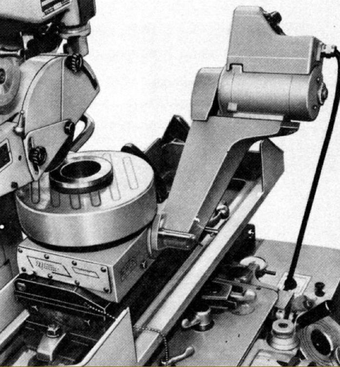
"Bowers" Inclinable Rotary Table. This unit was able to rotary grind wet or dry at angles from 0 to 45-degrees. The rotating magnetic chuck was driven by a sealed gearbox mounted on a sine table with a 5-inch (127 mm) sine bar setting. The gearbox was driven by a variable-speed 1-phase motor which, for increased capacity, was mounted on a moveable arm. |
|
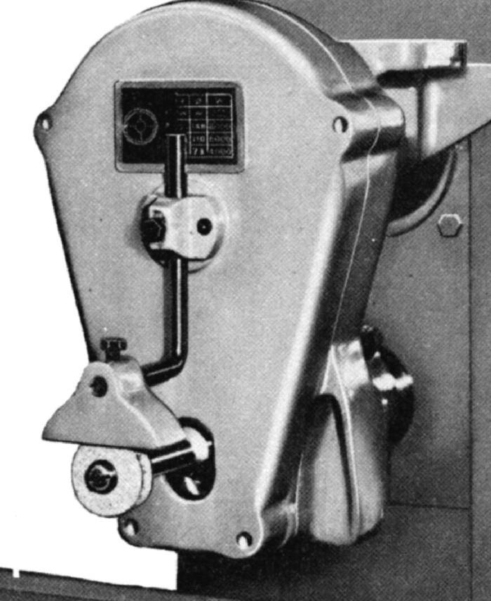
High Speed Grinding Attachment. To grind narrow slots and small radii, etc. this 3-speed unit was driven by belt from the main spindle at 4,000, 6,000 or 8,000 r.p.m. |
||
|
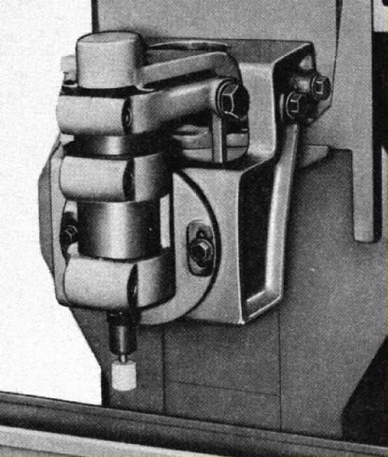
Vertical Grinding Attachment |
||
|
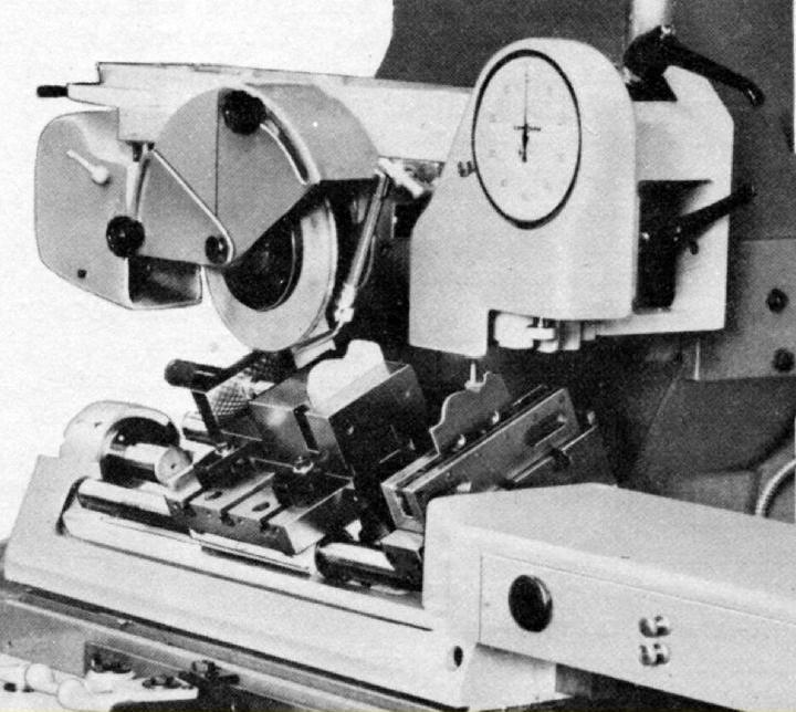
"Copiform" Surface/Profile Attachment. Made to fit a variety of Jones & Shipman grinders this unit adapted the host machine for accurate profile grinding. The working principle was simple but ingenious - a stylus being traversed over a template, using the cross and vertical feeds, whilst maintaining a zero setting on a large dial to which it was attached). The workpiece, set in line with the template, was passed under the grinding wheel on a reciprocating table. The grinding of vertical faces could also be accommodated by swivelled the template holder over to present them at an angle. |
||
|
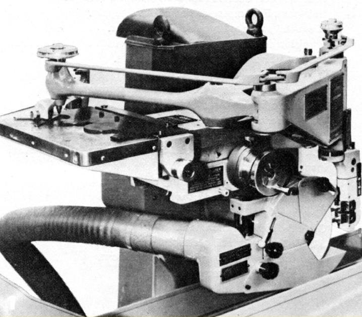
"Diaform" Wheel Forming Attachment. Made to fit many makes of grinder this unit was designed as a means of quickly and accurately "form dressing" (profiling) the grinding wheel. The shape was transferred pantographically from a prepared template and the wheel cut with a diamond-tipped tool. The template was made considerably oversized and the pantograph arm, manipulated by the operator, transferred the profile at a reduced ratio to the cutter. By this means both simple and complex shapes could be generated in a matter of minutes and increased accuracy obtained with the minimum of effort. |
||
|
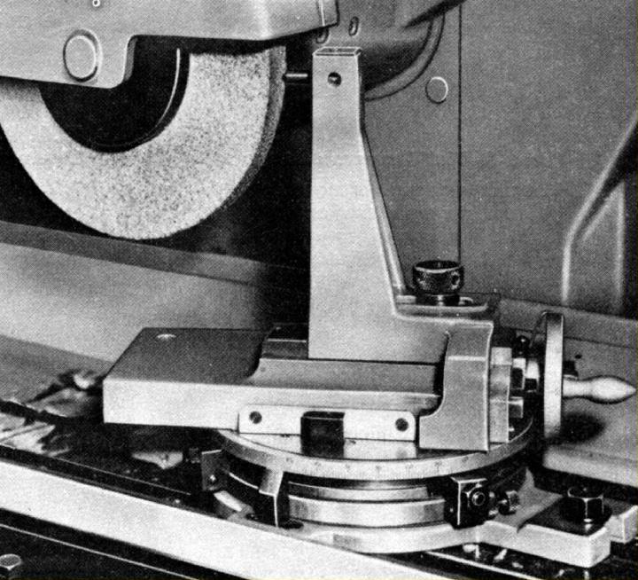
Radius/Angular Wheel Forming Attachment. |
||

|
"Diaform" Tangent/Radius Dresser. |
||
|
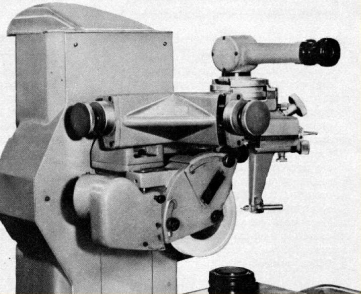
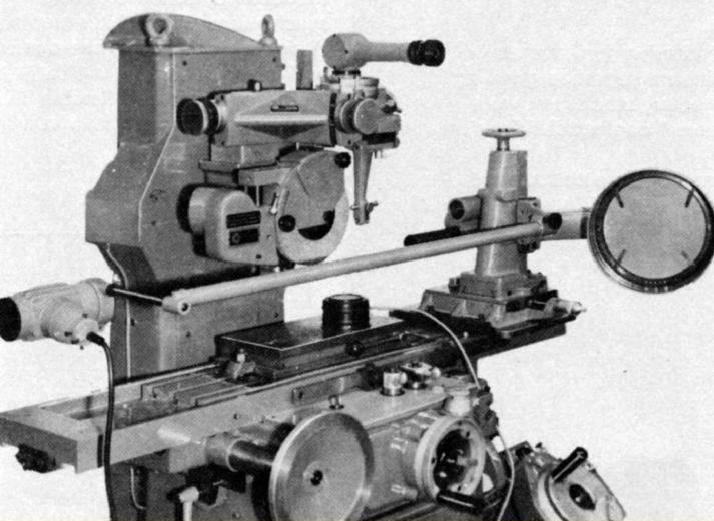
"P.G." Projectorscope Form Grinding Inspection Attachment. |
||
|
|
||
|
|||||||||||
|
|
||