 |
 |
 |
 |
 |
 |
 |
 |
 |
 |
 |
 |
 |
 |
 |
 |
 |
 |
 |
 |
 |
 |
 |
 |
 |
 |
 |
 |
 |
 |
 |
 |
 |
 |
 |
 |
 |
 |
 |
 |
 |
 |
 |
 |
 |
 |
 |
 |
 |
 |
 |
 |
 |
 |
 |
 |
 |
 |
 |
 |
 |
 |
 |
 |
 |
|
|
|
|
|
|
|
|
|
|
|
|
|
|
|
|
|
|
|
|
|
|
|
|
|
|
|
|
|
|
|
|
|
|
|
|
|
|
|
|
|
|
|
|
|
|
|
|
|
|
|
|
|
|
|
|
|
|
|
|
|
|
|
|
|
|
|
|
|
|
|
|
|
|
|
|
|
|
|
|
Massachusetts was the cradle of not only the American Revolution (and the state where the first shot was fired in the American War of Independence) but also the birthplace of the American Industrial Revolution. An important part of this industrial development centred on the town of Waltham, where the Waltham Machine Works were based - the "Waltham" lathe being one of their products (confusingly there was also a Waltham Watch Tool Company, who produced a similar high-quality precision bench lathe badged Waltham Watch Co.). Having enjoyed a head start in acquiring engineering expertise, Massachusetts became home to many makers of fine-quality machine tools amongst which the better known were Stark, the American Watch Tool Company, B.C. Ames, Wade and F.W.Derbyshire - who all manufactured the larger "precision bench" and much smaller watchmakers' lathes - Nichols (who made milling machines) and Rhodes with their convertible shaper/slotter. Waltham was also the first home of the well-known Van Norman Company who specialised in milling machine and later automobile equipment. Founded in 1888 by Charles E. and Fred D.Van Norman as the Waltham Watch Tool Company (to make tools for the watch-making trade) the Van Norman name appears not to have been used on their products until a few years later when they moved to Springfield.
Surprisingly late into the market - the standard-setting Stark bench lathe had been announced as early as 1862 - the first Waltham lathe appeared in 1899. However, it must have been an immediate success, the first export orders coming from England and Switzerland in the same year - both being highly critical, experienced and already well-developed markets for precision machine tools (the Swiss machine was sold through the agency of L. Ariste Gindrat, a citizen of that country who had lived in Waltham for many years). As result of that initial sale to Switzerland, over one hundred more machines followed with some examples, marketed by Breguet and Juvenia, being badged as if manufactured locally. The occasional Waltham lathe does come to light in Europe and, in 2009, a complete and original example was found in a Besanšon, (an hour's from the Swiss border), in a very long-established workshop, the finder reporting: ancient leather belts hanging all around and a smell of old grease remaining in the air As Waltham's reputation spread to the watch and clock makers and repairers of France and Germany, orders for standard and special machines began to arrive from them as well and, for the first ten or fifteen years of the Company's existence, a large percentage of its total output was exported.
Of conventional construction, and similar to competing makes, the bed had a single large T-slot down one side, a flat top and bevelled edges to locate the headstock carriage and tailstock. Being otherwise symmetrical, and available in lengths of 32 and 36 inches, it could "turned round" so that the slot faced either to the front or rear; this arrangement allowed a wide-range of interesting accessories to be mounted, some of which are illustrated below and on other pages. The headstock assembly was unusual in that, once the bolt holding the drive pulley had been slackened, the spindle could be withdrawn from its plain, parallel bearings without upsetting their fine adjustment. The spindle bearings were held in split, taper bushings with an adjusting nut acting on the outer bushing; the bearings could therefore be closed down onto the spindle whilst remaining perfectly parallel - the inside faces of these bushes also served as thrust bearings. A recent test found a Waltham spindle running true to within better than 0.00005" - a figure so fine that regular workshop measuring instruments were not good enough to resolve a final figure. The spindle did not carry a nose thread, instead the end was formed to accept both internal "wire" collets and external stepped types that required a tapered surface to pull down on. By making the spindle to this design (though no doubt a thread would have been supplied had the customer asked for it) the lathe was much easier and quicker to use for dedicated watch and clock work. If a chuck or faceplate was needed, ones fitted to collets could be supplied, sensibly arranged on the type that closed down on the 3-degree taper outer surface of the spindle nose. Unusually for a high-class precision bench lathes the largest diameter of the headstock pulley was against the right-hand headstock bearing instead of the smallest - an arrangement possible adopted to allow easier fitting of an optional (and very rare) epicyclic reduction gearing within the pulley. The official explanation, from a 1909 catalogue, states: ...As the larger part of the end pressure is on the rear bearing this part of the casting is made stronger and the large step of the pulley is placed next to the front bearing thus bringing the circles of index holes in the large flange of the pulley to a more convenient position than would otherwise be the case. Three circles of holes are provided, 48, 60, and 100. These should be only used for dividing work as for convenience in chuck operating we have provided another circle of holes in the smaller flange connection with a strong pin in the rear part of the casting. The head-stock is held firmly to the bed by two bolts......." The face of the largest-diameter pulley could carry up to three indexing rings, typically with 48, 60 and 100 holes, but no doubt able to be modified to a customer's precise requirements.
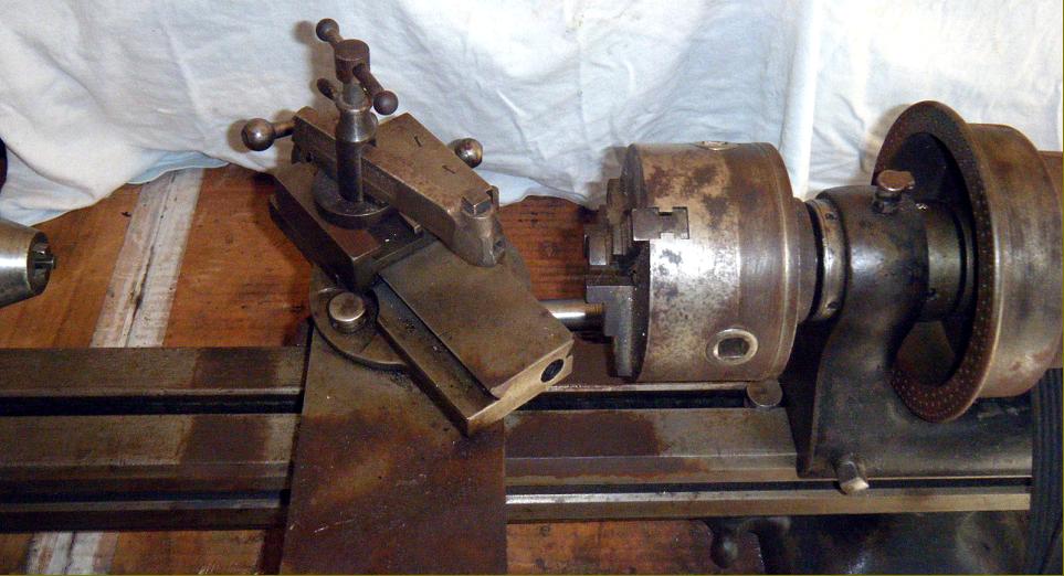
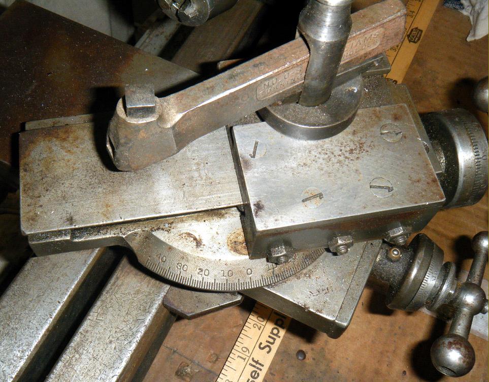
Two designs of compound slide were available, identical in all but the way that they fitted to the bed - the simpler of the two versions registering against the vertical way along the front edge (and retained permanently to it at right angles) the other fitted to a graduated base allowing it to be swivelled 45 degrees each way from the centre..
|
|
|
|
|
|
|
|
 |
|
|
|
|
 |
|
|
|
|
|
|
|
 |
|
|
|
|
|
|
A Waltham lathe fitted with changewheel screwcutting with drive to the top slide.
This was a very well engineered accessory; it was mounted by turning the bed round so that the single T slot faced the front and using it to hold two substantial brackets that carried the motion from changewheels to top slide. Unusually, this attachment did not, like the great majority of similar systems, use a universal joint in the drive system. The drive line was completely straight until it arrived at an enclosed gearbox just before the top-slide connection. This gearbox was ingeniously split about its centre line, and one half was able to pivot relative to the other, so accommodating the cross-slide movement that was necessary to position the thread-cutting tool; a glance at the picture above should make the operation of the system clear.
Gears were available to cut any thread between 5 and 100 t.p.i and, if the slide rests were equipped with metric screws, pitches in millimetres between 0.20 and 4.00 could be obtained as well.
|
|
|
|
|
|
|
 |
|
|
|
|
|
|
Waltham lathe fitted with "Chase" Master-Thread screwcutting. "Chase" screwcutting was developed by Joseph Nason of New York, who obtained US Patent No. 10,383 on January 3, 1854 for an "arrangement for cutting screws in lathes."
This picture shows clearly the well-proportioned items used on the Waltham to perform this early type of screwcutting. The bed was turned so that the T slot ran down the back of the bed; in the slot were three adjustable supports two of which carried the Master Thread (also known as a hob or leader) - whilst at the headstock end the third bracket supported an arm that carried additional gearing to extend the threading range.
A "half-nut", held in the base of an adjustable tool-slide, pressed on the thread and transmitted its form to the workpiece. The interconnection of the cutter holder and the half nut allowed the nut to be lifted out of engagement and the cutting tool returned by hand to the start of the thread without stopping or reversing the lathe; a little additional depth of cut could then be applied by the tool slide, the half-nut rested back on the master thread - and the cut restarted.
Whilst this system produced absolutely accurate threads, and was especially suited to delicate operations on thin-wall tubes used to construct such items as microscopes, the length of thread that could be cut, and the number of threads per inch or mm, depended upon the availability of the appropriate thread master.
In order to reduce the spindle speed for screwcutting, or larger faceplate work, Waltham offered a special headstock with a completely enclosed 4 : 1 ratio epicyclic-reduction gear.
A very simple form of this screwcutting mechanism can be seen on the Goodell-Pratt Pages whilst on the Stark, Pratt & Whitney, Ames, Potter and Wade pages alternative and more highly developed arrangements of the same system can be seen.
|
|
|
|
|
|
|
 |
|
|
|
|
|
|
Waltham Headstock - front of the spindle with its internal and (3-degree taper) external collet fittings.
The headstock assembly was unusual in that, once the bolt holding the drive pulley had been slackened, the spindle could be withdrawn from its plain, parallel bearings without upsetting their fine adjustment. The bearings were held in split, taper bushings with an adjusting nut acting on the outer bushing; the bearings could therefore be closed down onto the spindle whilst remaining perfectly parallel. The inside faces of the bushes also served as thrust bearings.
|
|
|
|
|
|
|
 |
|
|
|
|
|
Waltham headstock with collet draw tube, indexing holes at each end of the pulley, wick fed oilers and bed clamps.
|
|
|
|
|
|
|
|
|
|
|
|
|
|
|
 |
|
|
|
|
The enclosed front pulley gives away the identity of this "internally-geared" headstock. An epicyclic gear train, built into the cone pulley and activated by a single lever, produced a 4 : 1 reduction in spindle speed.
|
|
|
|
|
|
|
|
|
|
|
|
 |
|
|
|
|
Designed for use with the milling-slide attachments, this 8" diameter index plate, with 20 circles of holes, could be attached to the standard or geared headstocks.
|
|
|
|
|
|
|
|
|
|
|
|
 |
|
|
|
|
|
|
Waltham swivelling compound slide with standard toolpost
|
|
|
|
|
|
|
 |
|
|
|
|
|
Waltham swivelling compound slide fitted with a "Norman Patent" quick-set toolholder. The hardened toolpost was split on one side and clamped to a robust central post. The tall, knurled screw protruding from the top of the toolpost allowed fine adjustments to be made to the height setting. A similar design was used on the English Drummond M Type lathe. Note the location of the compound slide rest - instead of being bolted down against the bed's bevelled edges it is pulled up against a vertical surface.
|
|
|
|
|
|
|
 |
|
|
|
|
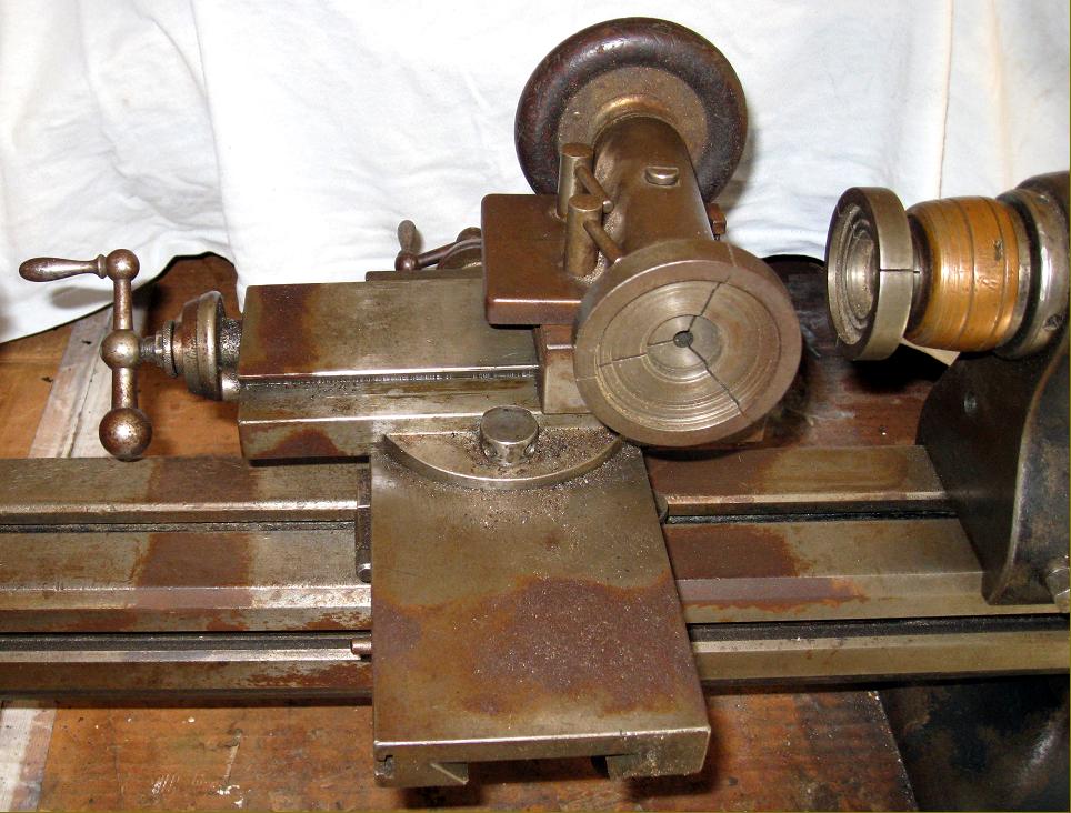
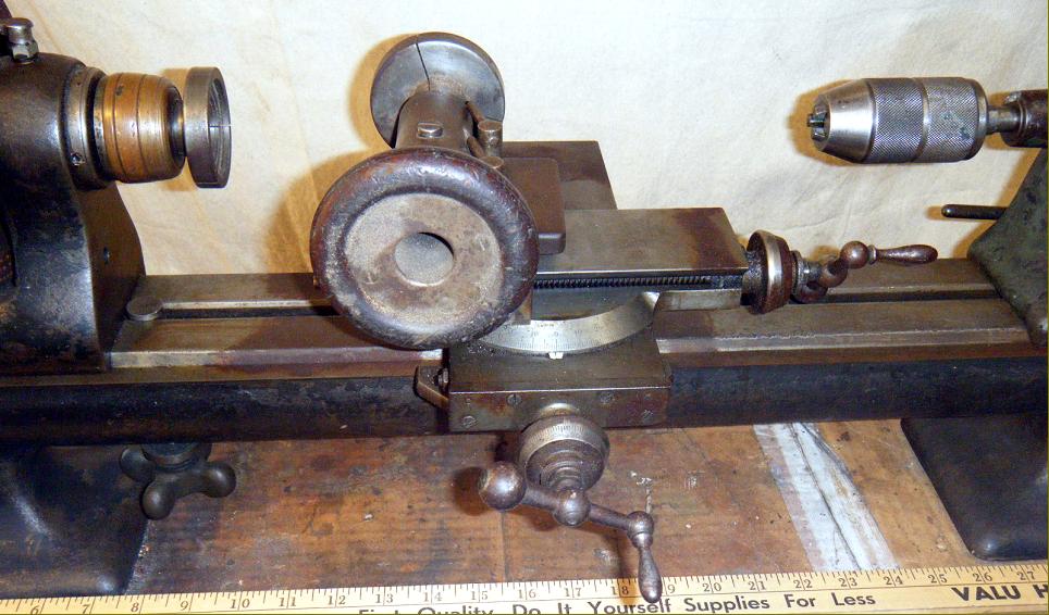
Costing one-and-a-half times as much as the basic lathe this wonderful accessory was a veritable technical tour de force. The slide, shown here sitting on the lathe compound slide rest, had two motions, vertical and horizontal (rather like the rare Boxford unit of recent times) and carried a gearbox, the input pulley for which can be seen in the picture. The gear drive passed through the face of the slide into a combined "milling and indexing unit" on which either stub cutters or an overarm-supported arbor could be mounted.
The method of operation could also be reversed, for the unit's spindle nose took the same fittings as the lathe headstock and, by employing the three circles of indexing holes, it was possible to hold a job whilst a cutter or grinding wheel (held in the headstock spindle) was applied to it.
|
|
|
|
|
|
|
|
|
|
|
|
 |
|
|
|
|
|
|
This "milling stand", as the makers called it, utilised the headstock and compound slide unit of the lathe in conjunction with a knee that could be raised and lowered by either quick-action lever or screw-operated feeds.
|
|
|
|
|
|
|
|
|
|
 |
|
|
|
|
A remarkable Waltham accessory - the powered filing attachment.
Those experienced with ordinary "filing machines" will know that they are not what the layman might think them to be - a rough-and-ready method of removing metal - but the exact opposite. A top-class filing machine was an expensive item - and an experienced operator could achieve almost miraculously-accurate results with one. They were not designed to be employed in general workshops but found a valuable niche in better-equipped toolrooms. Equipped with a five-inch diameter table that could be tilted to file any clearance angle, the Waltham unit could, whilst angled, then be rotated for one complete turn in the horizontal plane, making it possible to file a square corner, with a clearance angle at each side, with one setting of the work. The attachment was also available as a complete machine, as illustrated below. Its three-step pulley was designed to be driven not, as it may appear to the modern eye, by a V belt, but by a round leather "rope".
|
|
|
|
|
|
|
|
|
|
|
|
 |
|
|
|
|
|
|
Waltham filing accessory as a stand-alone complete
|
|
|
|
|
|
|
|
|
|
 |
|
|
|
|
|
Waltham precision bench lathe headstock and tailstock
|
|
|
|
|
|
|
 |
|
|
|
|
 |
|
|
|
|
|
The end face of the largest diameter pulley carried three indexing rings with 48, 60 and 100 holes.
|
|
|
|
|
|
|
 |
|
|
|
|
|
|
|
|
|
Pulley index marks clearly stamped into the headstock face. It is likely that rings with alternative numbers of holes would have been available
|
|
|
|
|
|
|
|
|
 |
|
|
|
|
|
|
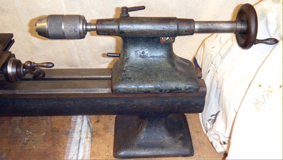
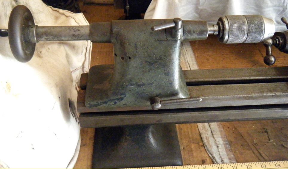
Simple split casting to lock the tailstock spindle. A fitting found on many precision bench lathes and a surprising one given that more effective "split-barrel" types were available
|
|
|
|
|
|
|
 |
|
|
|
|
 |
|
|
|
|
|
Tailstock graduations: the dial is marked at intervals of 0.005" and the spindle in tenths of an inch
|
|
|
|
|
|
|
 |
|
|
|
 |
|
|
|
|
 |
|
|
|
|
 |
|
|
|
|
 |
|
|
|
|
 |
|
|
|
|
 |
|
|
|
|
 |
|
|
|
|
 |
|
|
|
|
 |
|
|
|
|
 |
|
|
|
|
 |
|
|
|
|
 |
|
|
|
|
|
|
|
|
|
|
|
|
|
|
|
|
|
|
|


