 |
|
|
|
|
|
|
|
|
|
|
|
|
|
|
|
|
|
|
|
|
|
|
|
|
|
|
|
|
|
|
|
|
|
|
|
|
|
|
|
|
|
|
|
|
|
|
|
|
|
|
|
|
|
|
|
|
|
|
|
|
|
|
|
|
|
|
|
|
|
|
|
|
|
|
|
|
|
|
|
|
|
|
|
|
|
|
|
|
|
|
|
|
|
|
|
|
|
|
|
|
|
|
|
|
|
|
|
|
|
|
|
|
|
|
|
|
|
|
|
|
|
|
|
|
|
|
|
|
|
|
|
|
|
|
|
|
|
|
|
|
|
|
|
|
|
|
|
|
|
|
|
|
|
|
|
|
|
|
|
|
|
|
|
|
|
|
|
|
|
|
|
|
|
|
|
|
|
|
|
|
|
|
|
|
|
|
|
|
|
|
|
|
|
|
|
|
|
|
|
|
|
|
 |
|
|
|
 |
|
|
|
|
|
|
|
|
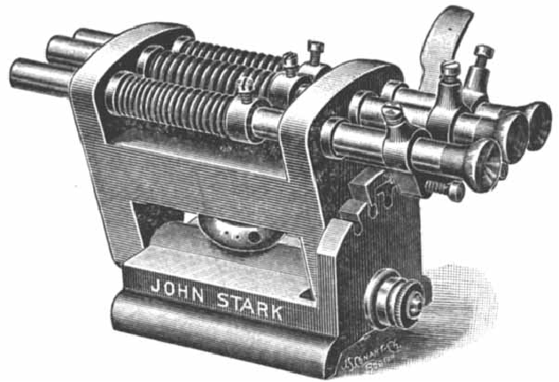
Lever-action Revolving Spindle Tailstock - intended for deep-hole, high-precision, small-diameter drilling this unit allowed a drill, held in a collet, to be rotated at very high speed by a round-rope drive from an overhead countershaft.
With tiny drills the problem is to attain the correct cutting speed; by rotating the headstock (holding the workpiece) in one direction and the drill in the other - at up to 10,000 rpm - an efficient cutting speed was more easily obtained.
|
|
|
|
|
|
|
|
|
|
|
|
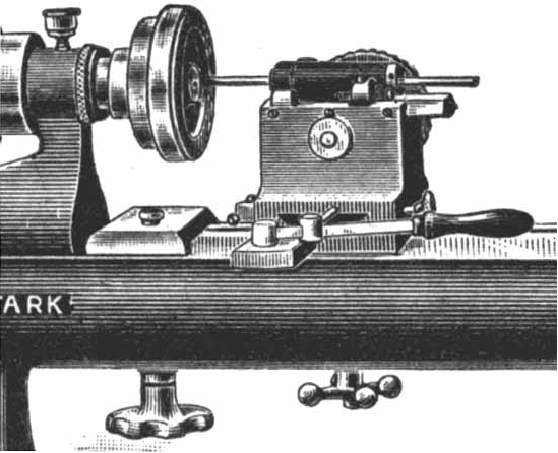
Sliding tailstock:
This light tailstock was intended for very sensitive drilling and reaming operations. The bushings through which the spindle slid were of hardened and ground tool steel and an adjustable stop - which doubled as a steady - was part of the standard specification.
|
|
|
|
|
|
|
|
|
|
|
 |
|
|
|
|
 |
|
|
|
|
|
|
|
|
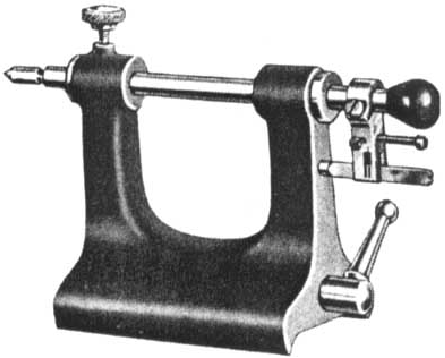
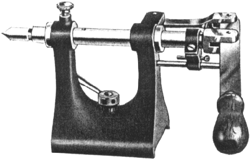
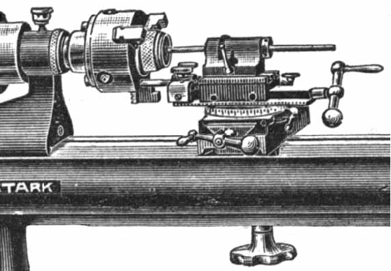
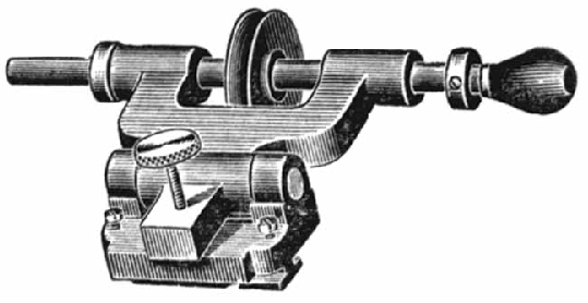
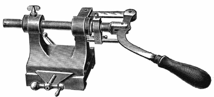
Lever-action tailstock:
Very fine control is far easier when exerted through the medium of a lever rather than a screw thread. Models were available to fit all sizes of Stark lathes.
|
|
|
|
|
|
|
|
|
|
 |
|
|
|
|
|
|
|
|
|
|
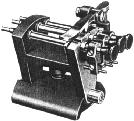
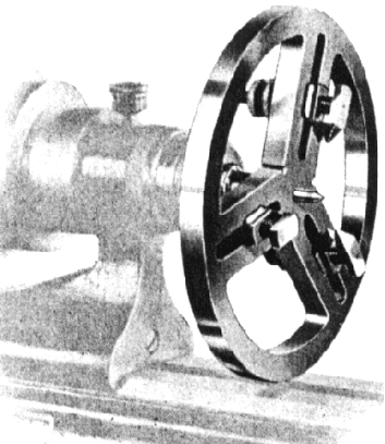
Three-spindle Tumble Tailstock:
This unit was intended to be employed where two or three tools could be used in succession on light production work. The three spindles, all of the "light sliding type", 6 inches long and fitted with adjustable depth stops, were mounted in a swing frame, pivoted on studs mounted in the base plate; the frame was indexed into each of its three positions by a spring-loaded pawl. Versions were available for all but the No. 5 lathe.
|
|
|
|
|
|
|
|
|
|
|
|
 |
|
|
|
|
|
|
|
|
|
|
|
|
|
|
|
|
 |
|
|
|
|
|
|
|
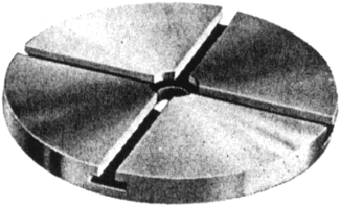
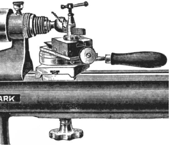
Universal Pump Centre:
A large version of the unit common on watchmakers' lathes. The three jaws could be locked into their slots and the clamps on the top of each slackened to enable work to be removed, and replaced, without losing the accuracy of the initial setting.
|
|
|
|
|
|
|
|
|
|
|
|
|
|
|
|
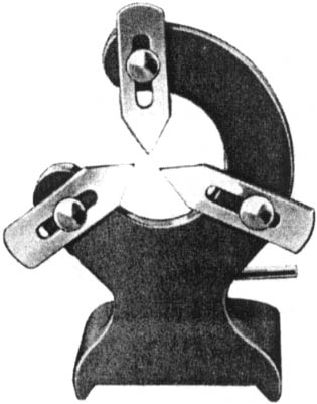
Fixed Steady with simple hand-set fingers
|
|
|
|
|
|
|
|
 |
|
|
|
|
|
|
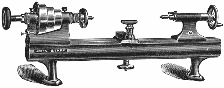
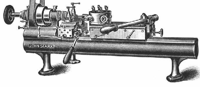
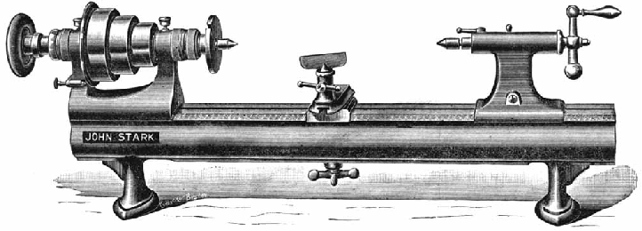
The basic Stark No. 3 Precision Bench Lathe with a simple hand-tool rest
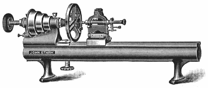
The Stark No. 3 7-inch swing Precision Bench Lathe was intended for use by "Electricians, Machinists, Astronomical and Surgical Instrument makers and for the manufacture of Fine Machinists' Tools and Machinery of every description". The capacity between centres on the 32-inch long bed was 18 inches and the through-collet capacity ranged from 0.020" to 0.400". On its introduction it was the only lathe of its type fitted with a spindle having the end thrust taken on a ball-bearing (anti-friction) race.
|
|
|
|
|
|
|
|
|
|
|
 |
|
 |
|
|
|
|
|
|
|
|
|
|
|
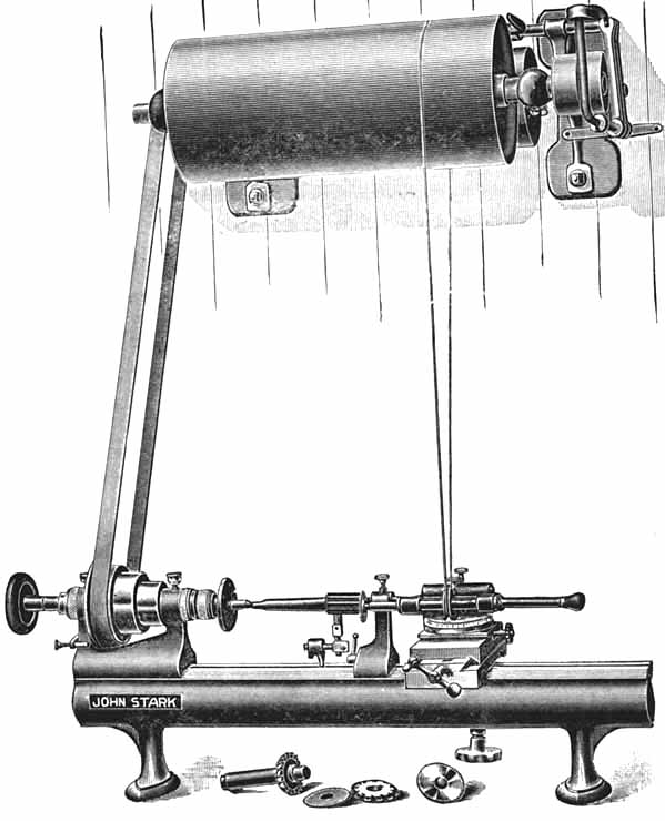
Toolpost-mounted Grinding Attachment:
This early version, which lacked the heavier build of later designs, was described in the first catalogs as a simple "grinding attachment" and was intended for internal and light external grinding.
The unit was driven by a round rope driven from a long drum attached to the overhead countershaft and was usually clamped into the position usually occupied by the tool post - and was therefore adjustable through all the normal movements and angles associated with the compound slide. Whilst Stark eventually listed four different models to suit the various sizes of lathe, all had the same 17/16" spindle travel.
|
|
|
|
|
|
|
|
|
|
|
|
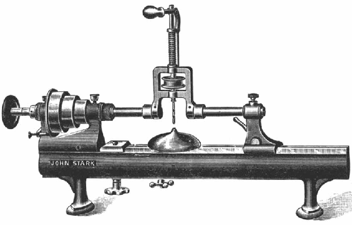
The screw-feed compound slide rest - which had no feed-screw graduations - fitted with a special boring toolholder with eccentric height adjustment - exactly like that used by Rivett on their "8-inch Precision".
|
|
|
|
|
|
|
|
|
|
|
|
|
|
|
 |
|
 |
|
|
|
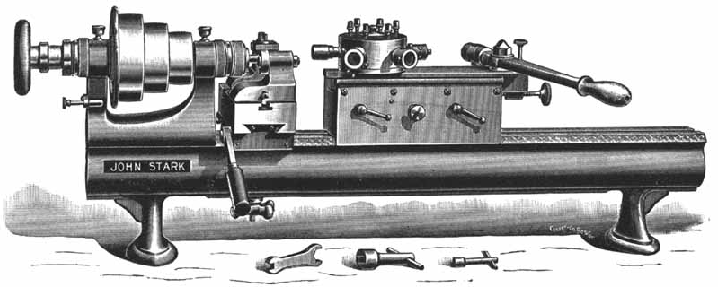
Stark No. 3 lathe fitted with an eccentric-height adjuster boring tool mounted on a special slide to speed up repetitive boring and facing work. Whilst the cross feed used an ordinary lever-operated arrangement, the longitudinal feed was by a rack-and-pinion mechanism engaged by a large handwheel at the back of the unit.
|
|
|
|
|
|
|
|
|
|
|
|
|
|
Ball-turning Rest. A useful accessory able to generate spherical shapes from 1/8 to 2 inches in diameter.
|
|
|
|
|
|
|
|
|
|
|
 |
|
|
|
|
|
The complete grinding assembly included the grinding head shown below, a special short, offset tailstock (around which the abrasive wheel could reach to grind pieces held between centres) and a countershaft unit with a long drum which allowed the compound slide with its grinding head to be placed anywhere on the bed.
|
|
|
|
|
|
|
|
|
|
|
|
|
|
 |
|
|
|
|
|
An unusual design of drill - able to be tilted to drill a hole at an angle, and with a capacity between the headstock and tailstock of 16 inches. How the workpiece was held down is not clear …..
|
|
|
|
|
|
|
|
|
|
|
 |
|
|
|
|
|
A Stark No. 3 Bench Lathe equipped as a rather large watchmaker's lathe with a faceplate (possibly with a "Pump Centre") and Jewelling Tool.
Stark advised that the Pump Centre was used for: "uprighting all kinds of Train Movements, such as Chronometers, Water and Gas Meters and all Electrical Trains constructed for Electricians", whilst the jewelling tool was for: "setting Lenses in Transit Instruments or setting Jewels in Chronometers or other train holes".
Several large cut-aways in the "faceplate" allowed the operator to see the work from behind as it rotated.
|
|
|
|
|
|
|
|
|
|
|
 |
|
|
|
|
|
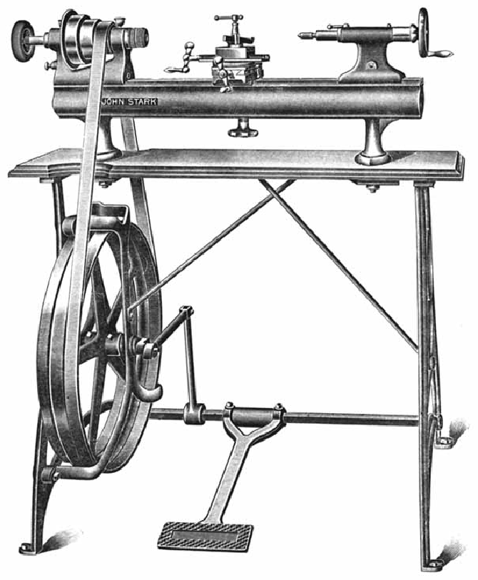
Stark No. 3 Lathe, with a screw-feed compound slide rest, on the maker's wonderful "Foot Power Attachment" - a treadle-equipped stand. On most other makes the flywheel assembly would have run on a simple, unsupported stud; on the Stark the outside of the stud is supported by a complex X-shaped structure bolted in four places to the top and bottom of the left-hand leg.
|
|
|
|
|
|
|
|
|
|
|
|
|
|
|
|
|
|
|
|
 |
|
|
|
|
|
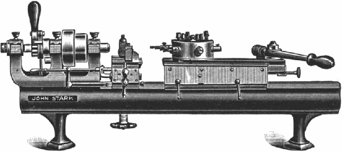
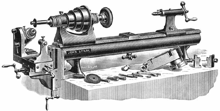
Stark No. 3 with the standard production items of a 6-station self-indexing turret and lever-action cut-off slide.
|
|
|
|
|
|
|
|
|
|
|
|
|
|
|
|
|
|
Stark No. 3
The Stark No. 3 lathe was also available fitted for production processes, usually with a 6-station turret and a cut-off (sometimes called a forming) slide. The rest of the lathe was absolutely standard but, in order to maximise the lathe's output, it was not unusual to see them fitted with a much more complex and expensive countershaft arrangement (which gave extra speeds and sometimes reverse) than those used for between centres and collet work.
Although it was not unusual to find early bed-mounted turrets with a mechanism which both drew back the slide and at the same time automatically rotated and indexed into position the 6-tool head, it was rarer for them to be fitted with six independent depth stops to control the feed of each tool. The unit illustrated on the Stark is an early version, with only a single stop, which would have meant a great deal more setting up time, and considerable difficulty in making small adjustments as the work progressed. This page has a picture of the later turret units with multiple depth stops.
Several makers of precision lathes produced "three-bearing" headstock models which were designed expressly for production use - usually in factories specialising in smaller components.
|
|
|
|
|
|
|
|
|
|
 |
|
|
|
|
|
Three-bearing Headstock
This special model, intended only for production work and without a screwed headstock spindle, was designed to overcome the inherent tendency of collets to draw work backwards when tightened - so making it difficult to obtain exact shoulder depths on repetition work. In use, the collet holding the workpiece remained stationary whilst, ingeniously, the headstock spindle moved forwards and backwards to tighten and release it. Unlike other makers, who positioned the third bearing on an outrigger which extended well beyond the end of the bed, Stark make their headstock a much closer, almost full-length fit. Unfortunately, this early version had a hand-operated collet closer whilst competitors used a foot-operated mechanism which left the operator's hands free to manipulate the cut-off slide, the turret head and feed material into the collet.
|
|
|
|
|
|
|
|
|
|
|
|
|
|
 |
|
|
|
|
|
To screwcut on the original Stark lathe required the use of a different headstock; on later versions this expensive change was no longer required, the entire mechanism being carried on brackets slotted into the rear T-slot behind a standard headstock.
|
|
|
|
|
|
|
|
|
|
|
|
|
|
|
Screwcutting on the Stark precision bench lathe:
Almost as soon as the first Precision bench lathe had first appeared in 1862, there was a demand for some form of screwcutting facility and before long most manufactures of this class of lathe were offering the facility in one (or both) of two ways: either a long-travel top slide through a universally jointed shaft from a train of changewheels driven from the headstock spindle, or by the "Chase" system, using a "Master Thread" and "Follower". The latter system was developed by Joseph Nason of New York who obtained US Patent No. 10,383 on January 3, 1854 for an "arrangement for cutting screws in lathes."
Stark choose to use the "Chase" system and their first lathe fitted with the device (but not later ones) required the use of both a different headstock and bed to that supplied as standard. The headstock was formed with two bosses cast onto its back surface in order to support the Master Thread, whilst the bed was given a T slot which ran the full length of the back, and another which occupied a proportion of the middle section of the front.
The Master Thread was driven by a train of gears connected to the headstock spindle in such a way that the number of threads that could be generated (from one Master) was multiplied by a factor of six. A long rod, held in brackets secured in the rear T slot carried a bracket holding, at its upper tip, a follower which engaged with the Master Thread (also known as a hob or leader) the rotation of the Master Thread caused the rod to slide in its support brackets and transmit its movement to a toolholder mounted in slide which could be adjusted for height as well as the depth of cut it was applying. Because the rod was free to move, the follower could be manually lifted out of engagement with the Master Thread and returned by hand to the start without having to stop or reverse the lathe. Once the follower was free, a little more depth of cut could be applied to the threading tools, the Follower returned to the start of the Master Thread - and the cut restarted.
Whilst this system produced absolutely accurate threads, and was especially suited to delicate operations on thin-wall tubes used to construct such items as microscopes, the length of thread that could be cut, and the number of threads per inch or mm, depended upon the availability of the appropriate thread master.
A very simple form of this screwcutting mechanism can be seen on the Goodell-Pratt Pages whilst similar arrangements, differing only in the detail of their construction, can be seen on the pages devoted to the precision lathe American makers: Pratt & Whitney, Ames, Potter, Waltham Machine Works and Wade.
|
|
|
|
|
|
|
|
 |
|
|
|
|
|
The precise height of the tool slide could be adjusted by a screwed rod. Instead of being held in a retainer secured to the bed - or in a sliding sleeve secured to the bed as on the Wade lathe - the Stark employed a more complicated system which relied upon a sliding plate secured in the front T slot.
|
|
|
|
|
|
|
|
|
|
|
 |
|
|
|
|
|
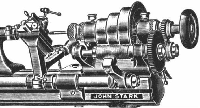
Detail of the early Stark "Chase" screwcutting system. Threads from 20 to 200 per inch could be generated with the standard set of leaders.
|
|
|
|
|
|
|
|
|
|
|
|
|
|
 |
|
|
|
|
|
|
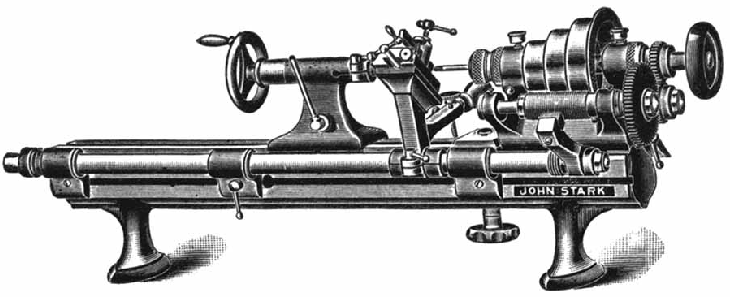
The original Stark No. 4 Precision Bench Lathe in basic form with a hand-tool rest and screw-feed tailstock.
The larger of the Company's two original models, the No. 4 lathe had a swing of 9 inches and a between-centres' capacity of 20 inches. 38 inches long overall, the machine accepted collets with a maximum capacity of 0.75 inches - the largest in its class at the time.
|
|
|
|
|
|
|
|
|
|
|
 |
|
|
|
|
|
The Stark No. 4 equipped with 6-station self-indexing turret assembly and a lever-action "cut-off" or "forming slide"
|
|
|
|
|
|
|
|
|
|
|
|
|
|
 |
|
|
|
|
|
In this early version of the Stark No. 4 lathe the headstock-end foot was extended to support a small compound table assembly which enabled simple horizontal milling to be undertaken. With the addition of a swivel-head Stark dividing head and tailstock the process of gearcutting - as demonstrated in the illustration - also became possible.
|
|
|
|
|
|
|
|
|
|
|
|
|
|
 |
|
|
|
|
|
|
|
|
In addition to the usual screw-feed and lever-feed tailstocks, Stark, like many other makers of high-class watch-making equipment, offered a special "Three-spindle Tumble Tailstock". This unit was intended to be employed where two or three tools could be used in succession on light production work. The three spring-loaded spindles - all of the "light sliding type", 6 inches long and fitted with adjustable depth stops - were mounted in a swing frame, pivoted on studs mounted in the base plate; the frame was indexed into each of its three positions by a spring-loaded pawl.
|
|
|
|
|
|
|
|
|
|
|
|
Early version of the Stark "Three-spindle Tumble Tailstock".
|
|
|
|
|
|
|
|
|
|
|
 |
|
|
|
|
|
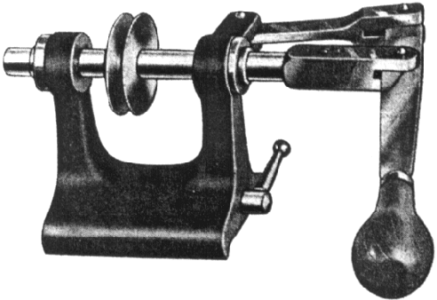
Lever-action tailstock on a screw-feed operated set-over base. The later version of this unit had a much wider base slide.
|
|
|
|
|
|
|
|
|
|
|
|
|
|
 |
|
|
|
|
|
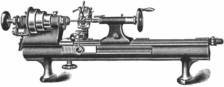
Standard Stark screw-feed tailstock. This early version had an ordinary barrel (spindle) which became less well supported the further out it came. Later versions were built with one of the trade-marks standard of the precision lathe, a long barrel which was fully supported at both ends of its travel. The section of the casting between base and barrel had a very thin cross section - a point not obvious in this view.
|
|
|
|
|
|
|
|
|
|
|
|
|
|
 |
|
|
|
|
|
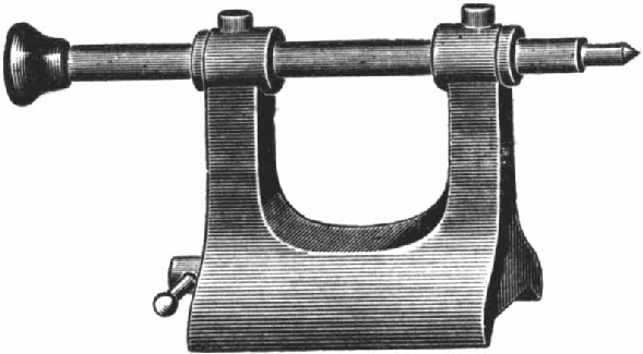
The very simplest of the Stark tailstocks was the traditional "sliding-barrel" type - operated by pushing and pulling on the ebony or hardwood end cap.
|
|
|
|
|
|
|
|
|
|
|
|
|
|
|
|
|
|
|
|
|
|