email: tony@lathes.co.uk
Home   Machine Tool Archive   Machine-tools Sale & Wanted
Machine Tool Manuals   Catalogues   Belts   Books  Accessories


Russian "Stankoimport" 1K62 Lathe
An Operation & Maintenance Manual together with a separate Parts Manual are available for 1K62. Literature for other Russian machine tools is also available

Stankoimport was not a manufacturing company but the machine-tool export arm of the USSR. The organisation offered a wide variety of machines, all well specified and very keenly priced to undercut Western manufacturers and so bring in much desired and very necessary foreign currencies.
Sometimes found badged by the English agents as a
Hartle-Stedall, this was a very heavily built lathe with a generous capacity, an excellent speed range and with a squat, powerful appearance slightly reminiscent of the English Holbrook. Sold from the late 1950s onwards it was of "normal" precision by Soviet standard and not the most precise of the lathes that they manufactured - but was it was robust  The Moscow factory "A. I. Efremov Krasnyi Proletarii Moscow Machine-tool Plant" produced slightly more than 200,000 examples of the IK62, making it the most ubiquitous in its size range. Other plants were also involved in its manufacture, or at least ones with slight modifications, but engineers in the know, understanding that the Moscow-built examples were of superior quality, still look for the letter "K" in the name.
With a centre height of 8 inches the lathe ordered with bed lengths able to take 28, 39.75 or 56 inches between centres. As an example of the machine's ability under test, one at the works of Broomfield Engineering in Folly Hall, Huddersfield, was observed reducing a 1
5/8" diameter mild-steel bar down to 1/4" in one pass using a tungsten-carbide tipped tool at 1000 r.p.m. with a feed rate of 0.006" per rev. Other users report that drilling a 50 mm (2-inch) hole in one pass is easily accomplished, as it threading into a hole using a 40 mm tap. Another feature that endears it to users is a clutch so sensitive that even allows key-holes in the chuck can to be brought to the front and thread cutting done so precisely that one turner found it easy to make a 500 mm long, 25 mm diameter drill bit, cutting the spirals using with the longest pitch available
Induction hardened, the bed was carried on separate headstock and tailstock plinths and met that essential requirement for a toolroom lathe in being almost as wide as twice the centre height, in this case 16 inches. Especially deep walls were used, strongly cross braced and with the carriage ways of the traditional V and flat type.
Drive came from a 13.5 h.p., 1500 r.p.m. motor mounted inside the headstock-end plinth and then by five V-belts to the all-geared headstock, the drive passing through a sliding clutch. 24 forward speeds were available, with 12 in reverse, the range being from 12.5 to 2000 r.p.m. - the former slow enough to allow the largest faceplate-mounted jobs to be turned at the correct speed and the latter fast enough for fine finishing work on smaller diameters. While a conventional headstock was offered with a speed dial positioned on the left of the headstock's front face and surrounded by settings visible through rectangular openings spaced around it and engagement by a lever to its right, it is thought that some versions may have had a pre-selector box found on other models of "Stankoimport" lathes.
On the conventional headstock the right-hand lever for gear shifting could be used with running motor and the clutch disengaged - though it was better to switch off the motor before operating the speed selector on the left side. The right and left (or forward and reverse) speeds were not the same, the reverse being around 1.2 or so times faster so as save precious working time on the "empty" cycle of thread-cutting and other operations. Running in ball races, the headstock shafts carried hardened, shaved and tooth-rounded gears in a chrome alloy steel; lubrication was by a mechanically driven plunger pump, oil being fed through a filter set above the gears and then onto a tray from where a network of holes and pipes distributed it to various parts of the headstock - a separate feed being directed into the front headstock bearing. Thought to have been bored through to clear a 2-inch bar, the forged spindle carried a No. 5 Morse taper in its nose and ran, at the front, in adjustable taper roller bearings.
Electrical control of the spindle stop and start was by push-buttons mounted on the saddle (in the manner as also used, for example, on the Harrison 17-inch). The stop button energised a reversing current to brake the spindle and, when stopped for more than 20 seconds, the drive motor automatically shut off.
Continued below:

Continued:
Connected to the 12 mm pitch leadscrew was a full screwcutting and feeds' gearbox, pressure lubricated and able, in its basic setting, to generate English pitches from 2 to 24 t.p.i., inch, metric from 1 to 12 mm, module from 0.5 to 48 and diametral from 96 to 1 D.P. It was also possible to cut spirals with pitches from 3/8" to 7/16" and, according to the handbook, to generate "Archimedes" spirals, like the ones inside self-centring chucks. In addition, a separate drive (by what the makers called
specially selected changewheels) could be fitted that by-passed the gearbox and allowed "high-accuracy" pitches to be generated - though how this arrangement offered any real advantage was not made clear. It was also possible, In order to extend the threading range a two-position knob, mounted on the front face of the headstock, enabled the ratio of the drive to the gearbox to be changed. In one setting, using spindle speeds from 12.5 to 40 r.p.m., coarse pitches 32 times the standard ratios were generated and in the other, with spindle speeds from 60 to 160 r.p.m., pitches could be increased by 8 times the setting on the gearbox drum.
A second knob, alongside the ratio selector, changed the carriage feed direction from left to right and also allowed, in its central position, for the spindle to be turned independently of the feed gearing and indexed round when multi-start threads were being cut - the axial settings being engraved on a plate surrounding the end of the spindle. The gearbox provided 42 sliding and surfacing feeds, the rate depending upon the spindle speed range selected: at any speed the sliding feeds ranged from 0.0027" to 0.081" per revolution of the spindle with surfacing set at half the rate (0.0013 to 0.081") while with the spindle running at between 50 and 630 r.p.m. feed rates ran from 0.081" to 0.163" sliding and 0.040" to 0.081" across.
Engagement of the drive from gearbox to leadscrew or power shaft was by a third-rod system with a control lever positioned by the gearbox and a second pivoting from the apron's right-hand face (and so travelling with it). The required pitches and feeds were obtained by a large rotary drum with,  on its face, a concentric disc equipped with either two or four ball-tipped handles. Pulling the handles right out allowed the inner section to be rotated to select one of four positions, a scale appearing at the top showing the range available. A particular setting from the range was then chosen by moving the disc inwards to an intermediate position and rotating it to bring a pointer in line with the figure required. Finally, pushing the disc fully in locked the setting, the whole operation taking less time to perform than to explain…...
Sliding and surfacing feeds, in both directions, were transmitted by four fine-tooth clutches built into the apron, quick and positive control being - unusually -  by a single joy-stick-like lever mounted on the right-hand face of the apron. Rapid power traverse in all directions was also fitted, this being engaged by a button on top of the joystick with a 1.3 h.p., 1500 r.p.m. motor, mounted in a recess at the tailstock end of the bed driving the power shaft through a V-belt. The system gave a sliding rate of 134 inches per minute with the feed shaft aromatically disconnected from the screwcutting gearbox by an over-run clutch incorporated within it. So well set-up was this system that operators, if they needed to move the carriage more than 10 mm or so, used the rapid traverse.
In order to protect the drive train, the apron incorporated a claw-type safety clutch that released once a pre-determined load had been reached; this device could also be tripped by using a stop on the bed - although this facility was not included on the cross-slide feed. As the carriage moved it automatically engaged a plunger type oil pump that distributed lubricant around the apron with a supply also fed to the bed and cross-slide ways; carriage travel was measured by a drum-type micrometer dial fitted to the face of the apron, this being graduated at intervals of 0.05".
Using conventional V-edged slides, the compound slide assembly had good sized zeroing micrometer dials and a split cross-feed screw that could be adjusted to remove backlash; cross-slide travel was 10 inches and 5.5 inches for the top slide, the latter able to be swivelled 90° each side of zero and fitted, as standard with a 4-way toolpost able to take tools up to 1-inch square.
Substantially built, the massive tailstock could be set over on its base plate for the turning of slight tapers and held a hardened steel barrel equipped with a massive No. 5 Morse taper. For heavy-duty work it was possible to arrange the tailstock for power drilling, this being achieved by bringing the carriage back close to the unit and arranging the cross slide so that an L-shaped section of metal plate could be mated with a similar piece connected to the tailstock's base. A lever-operated clamp at the end of the tailstock was then adjusted so that the base was held in close contact with the bedways - yet sufficiently free to slide as the carriage advanced towards the headstock using a slow feed rate. When the tailstock was used with a centre to support work between centres, or for drilling by hand, it was locked to the bed by two bolts, tightened by a loose, self-hiding spanner. On some models, especially those to be operated by female workers who had not been in the Soviet shot-putting team, the tailstock could be equipped with a high-pressure air supply that provided a cushion between it and the bed.
Electrical equipment was held in two compartments: one was mounted inside the left-hand cabinet leg and the other externally behind the tailstock end of the bed; the latter had an ammeter to show the load on the cutting tools and contained fuses and relays, etc. together with switches for the isolator, coolant, work light and, when fitted, the hydraulic copying attachment. The electrical circuit provided no-voltage isolation and overload protection for the three electric motors (main, coolant and power rapid-feed) with all circuits fused. The maker's also offered to fit custom-design electrical fittings should the customer have desired them.
Supplied with each new 1K62 was a complete set of electrical equipment, a coolant system rear splash guard, catchplate, two Morse centres for headstock and tailstock, headstock reduction sleeve, longitudinal carriage stop, travelling steady, extra changewheels, oil gun, a taper-pin puller, circlip pliers, seven spanners, a socket wrench, screwdriver, an Operation, Maintenance and a separate and Parts' Manual.

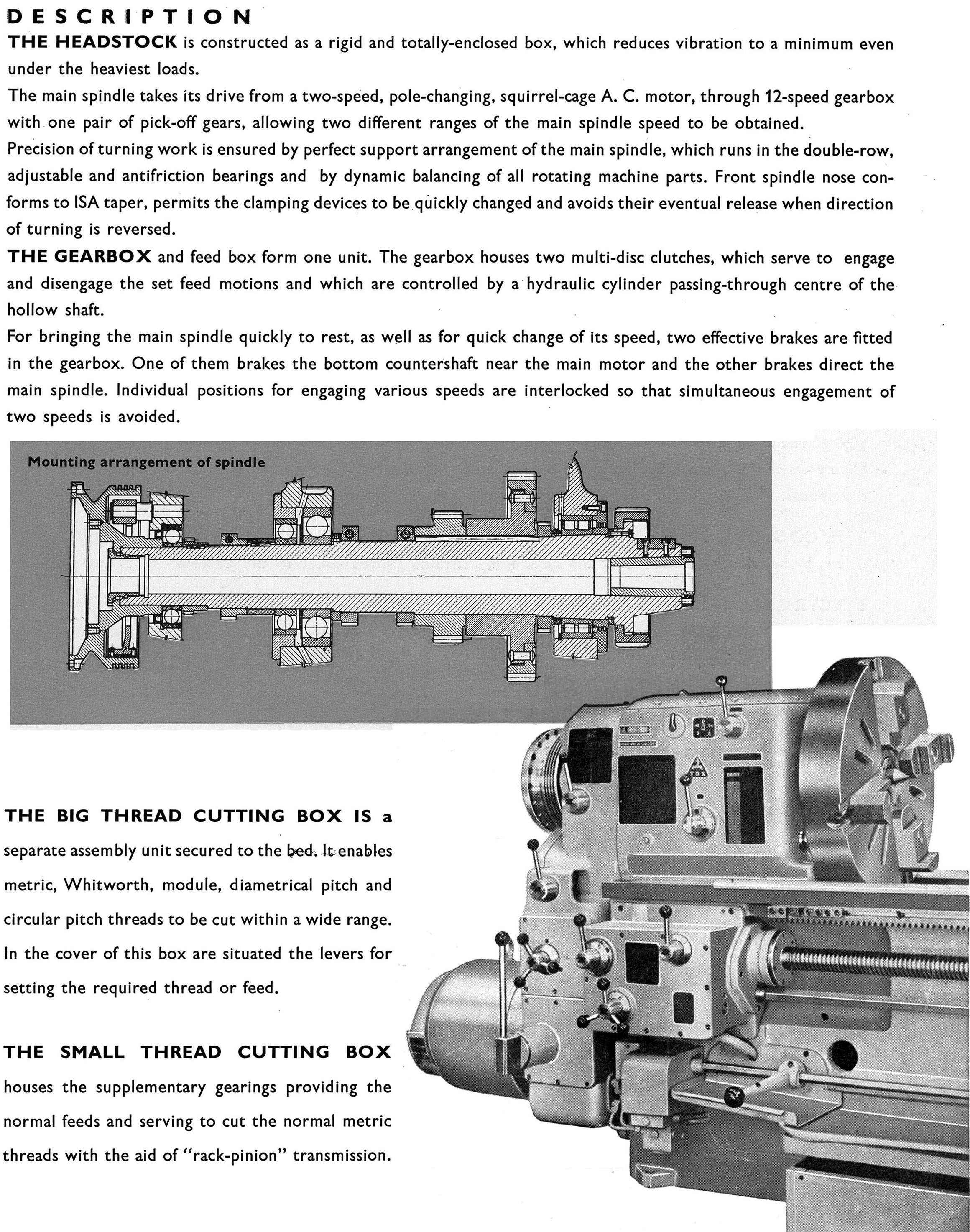
Spindle speeds were controlled by two levers on the front of the headstock - the one nearer the end face being set with the aid of a chart to give the desired range, the settings being visible through rectangular openings around the lever. To engage the specific speed, the second lever was turned until a pointer lined up with the desired setting.

Running in ball races, the headstock shafts carried hardened, shaved and tooth-rounded gears in a chrome alloy steel; lubrication was by a mechanically driven plunger pump, oil being fed through a filter set above the gears and then onto a tray from where a network of pipes distributed it to various parts of the headstock - a separate feed being directed into the front headstock bearings.

A full screwcutting and feeds' gearbox was fitted, pressure lubricated and able to generate inch, metric and module pitches, with a separate drive by changewheels also included that by-passed the gearbox and allowed "high-accuracy" pitches to be generated - though how this arrangement offered any real advantage was not made clear. It was also possible to generate spirals with pitches from 3/8" to 7/16".

As the carriage moved it engaged a plunger type oil pump that distributed lubricant around the apron with a supply also fed to the bed and cross-slide ways; carriage travel was measured by a drum-type micrometer dial was fitted to the face of the apron, this being graduated at intervals of 0.05".

Sliding and surfacing feeds, in both directions, were transmitted by four fine-tooth clutches built into the apron, control being - unusually -  by a single joy-stick-like lever mounted on the right-hand face of the apron. Power traverse in all directions was also fitted, this being engaged by a button on top of the joystick with a separate motor, mounted at the tailstock end of the bed, driving the power shaft through a V-belt. The system gave a sliding rate of 134 inches per minute with the feed shaft aromatically disconnected from the screwcutting gearbox by an over-run clutch.

Showing the V-belt drive from motor to the power-shaft to drive the rapid feeds

Substantially built, the tailstock could be set over on its base plate for the turning of slight tapers and held a hardened steel barrel equipped with a massive No. 5 Morse taper. For heavy-duty work it was possible to arrange the tailstock for power drilling, this being achieved by bringing the carriage back close to the unit and arranging the cross slide so that an L-shaped section of metal plate could be mated with a similar piece connected to the tailstock's base. A lever-operated clamp at the end of the tailstock was then adjusted so that the base was held in close contact with the bedways - yet sufficiently free to slide as the carriage advanced towards the headstock using a slow feed rate. When work was supported by a centre, or the tailstock used for drilling by hand, it was locked to the bed by two bolts, tightened by a loose, self-hiding spanner.

Electrical equipment was held in two compartments: one was mounted inside the left-hand cabinet leg and the other externally behind the tailstock end of the bed; the latter had an ammeter to show the load on the cutting tools and contained fuses and relays, etc. together with switches for the isolator, coolant, work light and, when fitted, the hydraulic copying attachment. The electrical circuit provided no-voltage isolation and overload protection for the three electric motors (main, coolant and power rapid-feed) with all circuits fused. The maker's also offered to fit custom-design electrical fittings should the customer have desired them.

email: tony@lathes.co.uk
Home   Machine Tool Archive   Machine-tools Sale & Wanted
Machine Tool Manuals   Catalogues   Belts   Books  Accessories


Russian "Stankoimport" 1K62 Lathe
An Operation & Maintenance Manual together with a separate Parts Manual
are available for 1K62. Literature for other Russian machine tools is also available