|
Home Machine Tool Archive Machine-tools Sale & Wanted Société Genevoise d'Instruments de Physique Operation & Maintenance Manuals are available for most SIP Jig Borers SIP Home Hydroptic 6A & 7A Jig Borer 1-H Jig Borer 2P Jig Borer 3K Jig Borer 4G Jig Borer 5E Jig Borer 8P Accessories Jig Borers 1920s No. 2C and No. 3 Tooling Cabinet |
||
|
|
|
|
|
|
|
|
||
|
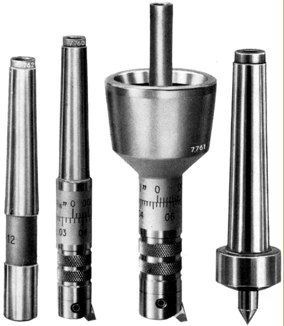
From the left: |
||
|
|
|
|
||
|
|
||
|
|
|
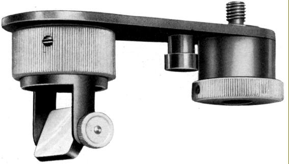
Additional Optical Device--for the simultaneous viewing of the workpiece and the tool in the viewing microscope |
||
|
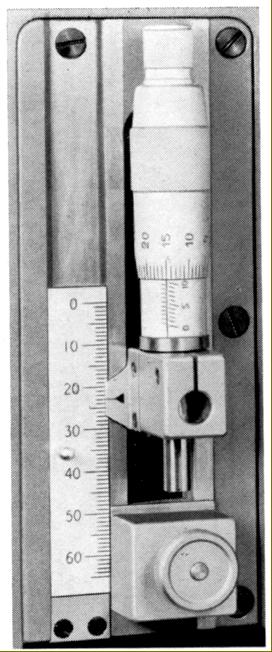
Depth-measuring device with micrometer stop. This unit could be mounted instead of the standard-fit dial indicator. Read in 0.001 or 0.01 mm. The unit shown has metric graduations. |
||
|
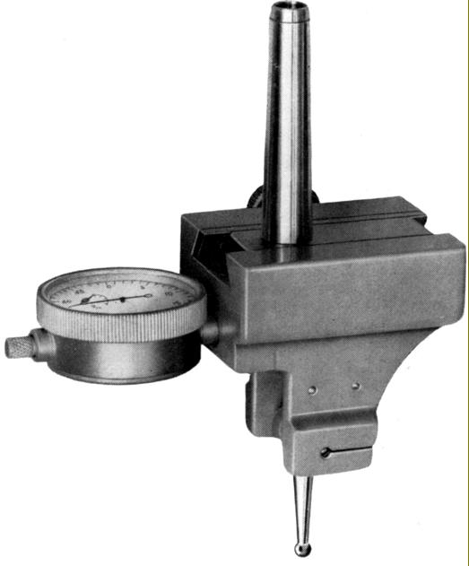
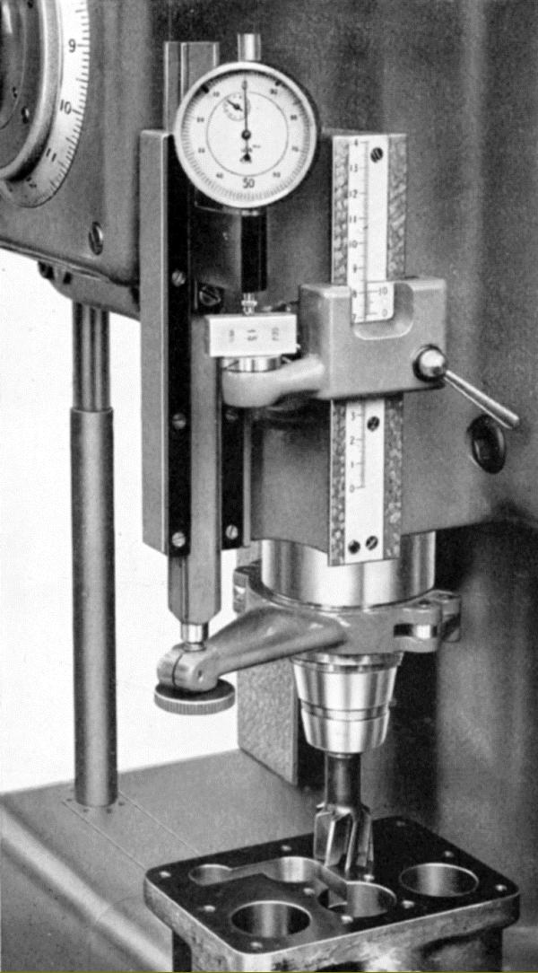
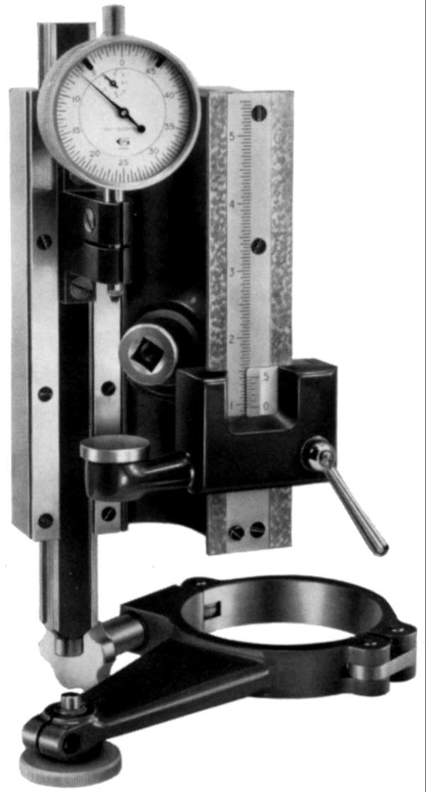
Various options were available to measure downfeed. These included a bolt-on assembly of ruler, slip gauge and very sensitive dial indicator. If the job needed boring to a depth of up to 3/8" (10 mm) the dial indicator could be used by itself. Used as a "sliding caliper" the dial indicator was first set to zero by moving the clamp-on ruler frame upwards. The support was then lowered to give the correct reading that could be read (by including the vernier reading on the vertical ruler) to within 0.005" (0.1 mm). For more accurate readings a gauge block (or blocks) that corresponded to the required boring depth could be placed on a support beneath the dial indicator. With the setting made, the bocks were removed and the machining started. As the job continued, the dial indicator moved downwards until it contacted the support plate and read zero - the accuracy obtained being to within 0.0005" (0.01 mm). |
|
|
||

|
|
|
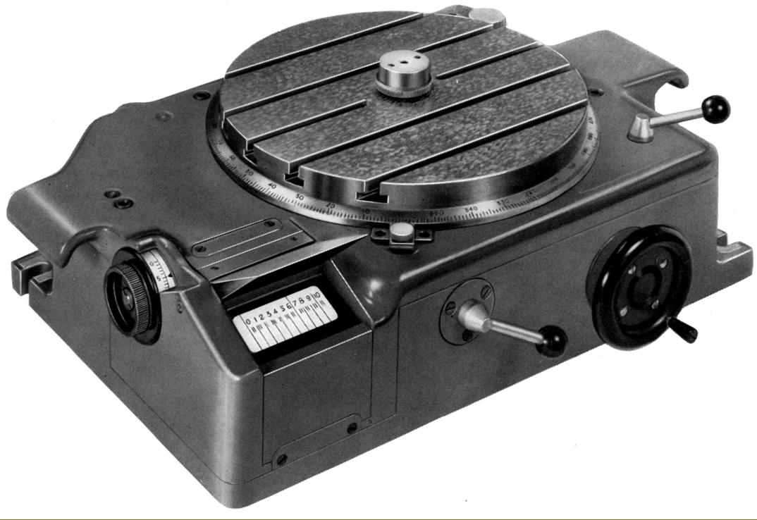
8.625" (220 mm) SIP Rotoptic-1 Optical Circular Dividing table with settings shown on a viewing screen and read from a built-in circular ruler made to standard scale accuracy. Rapid readings down to 1 second of arc could be achieved. |
|
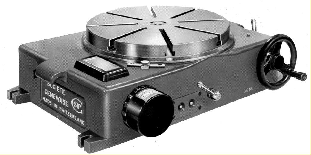
For the No. 2P a special No. 2 version of the Rotoptic Optical Circular Dividing Table was offered. With a 11.75-inch (300 mm) table this had, like the No. 1 model, readings shown on a viewing screen projected from a built-in circular ruler made to standard scale accuracy with quick settings down to 1 second of arc possible. |
|
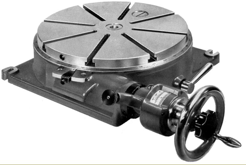
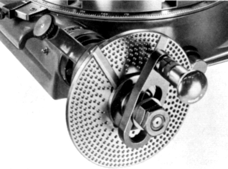
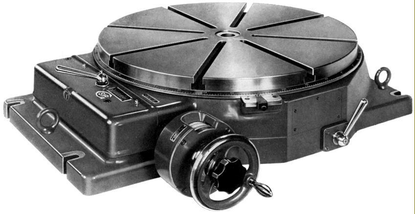
PD-3 Circular Dividing Table 13.75" (2350 mm) in diameter. The PD Series of tables also included the PD-4 ( 173/4"/450 mm); PD-5 235/8"/600 mm diameter and PD-6 235/8"/600 mm diameter. |
||
|
|
|
|
|
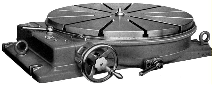
Type PD-6 Mechanical Circular Dividing 235/8" (600 mm) . A conventional, hand-operated version of the Rotoptic-6 that used worm-and-wheel gearing with readings down to 1 second of arc. |
|
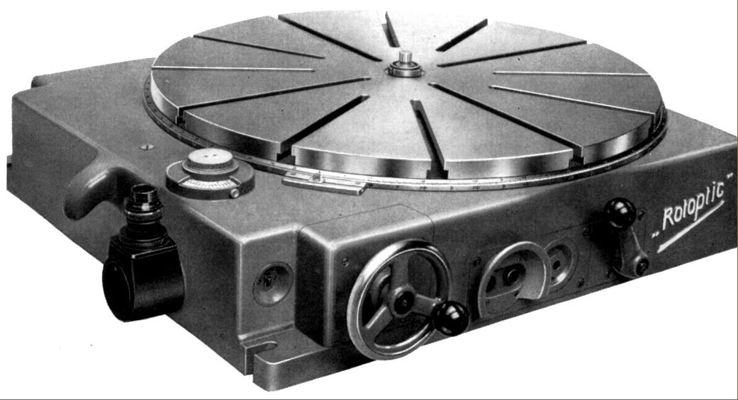
Motor-driven "Rotoptic-6" Circular Dividing Table with optical read-outs from a built-in master circular scale. This massive unit was designed to cope with the rigors of machining heavy jobs and rotated on a special large-diameter ball bearing. Readings down to 10 minutes of arc could be set under motor power with a further improvement down to 1 second being set by a handwheel with a vernier scale. The final setting was achieved by using a microscope to centre a projected line from the master circular scale between a fork on the viewing screen. |
|
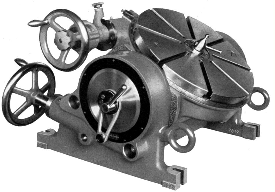
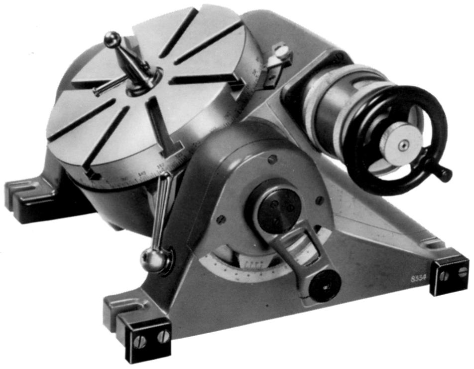
Type P1-4 (300 mm) and PI-5 (450 mm) Tilting Rotary Table with worm-and-wheel gearing. Theses units allowed the boring of holes and milling of faces to be accomplished at compound angles. Rotation angles were read to within 1 second of arc with tilt angles able to be set to within 1 minute of arc on the vernier of a lateral division circle. |
|
|
|
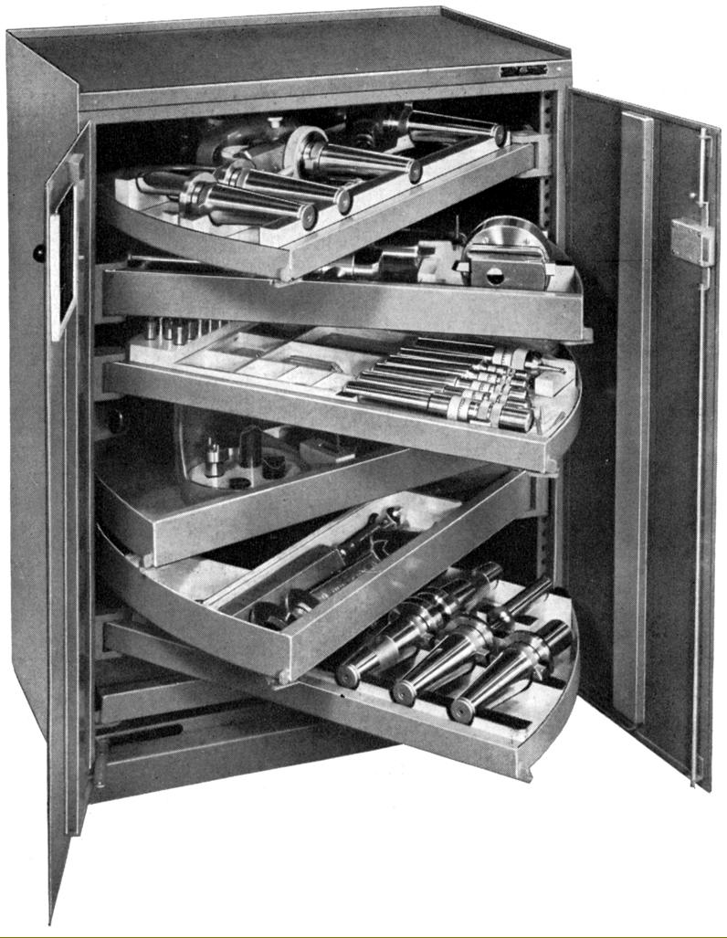
Typical very robust SIP floor-standing 40" x 30" x 20" (1000 x 750 x 500 mm) tool cabinet with seven very heavy-duty swing-out shelves each able to take a load of 200 lbs (100 kg). Six of the shelves were lined with felt to protect the edges of cutting tools. Photographs of a SIP tooling cabinet can be found here |
|
Home Machine Tool Archive Machine-tools Sale & Wanted Société Genevoise d'Instruments de Physique Operation & Maintenance Manuals are available for most SIP Jig Borers SIP Home Hydroptic 6A & 7A Jig Borer 1-H Jig Borer 2P Jig Borer 3K Jig Borer 4G Jig Borer 5E Jig Borer 8P Accessories Jig Borers 1920s No. 2C and No. 3 Tooling Cabinet |
||