|
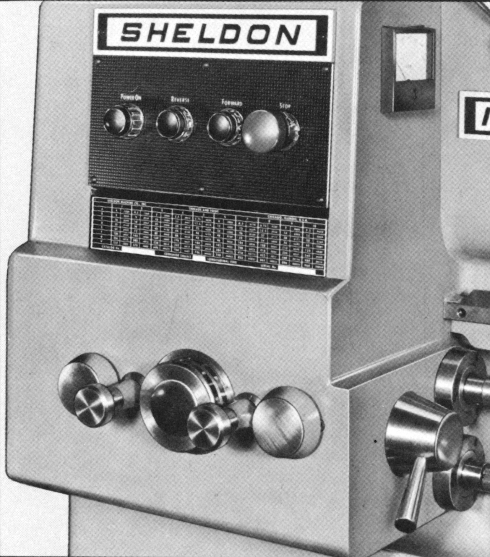
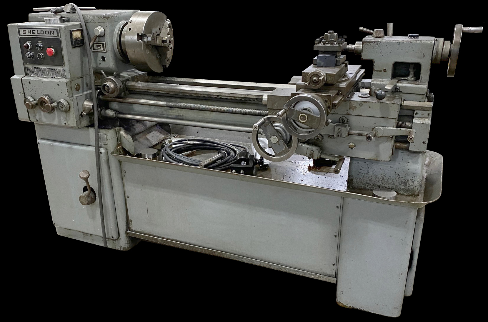
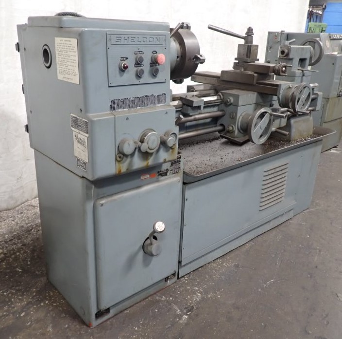
Introduced during the late 1970s and built until perhaps 1982, the Sheldon R-Series lathes - fitted with distinctive dial-change screwcutting gearboxes - were directly equivalent to the Colchester Colchester Master 2500 (Clausing Models 8014/15/16/17), Triumph 2000 (Clausing 8030 Series) and Mascot 1600 (Clausing 8050 Series). Both makes were a revolution in styling and specification and, though they may have lacked mechanical novelty, were a strong reminder that even machine tools are subject to the vagaries and whims of fashion. With their distinctive 'square' styling, ergonomically-designed controls and bright finishes, the new lathes and their angular styling made competing machines look distinctly dowdy and old-fashioned.
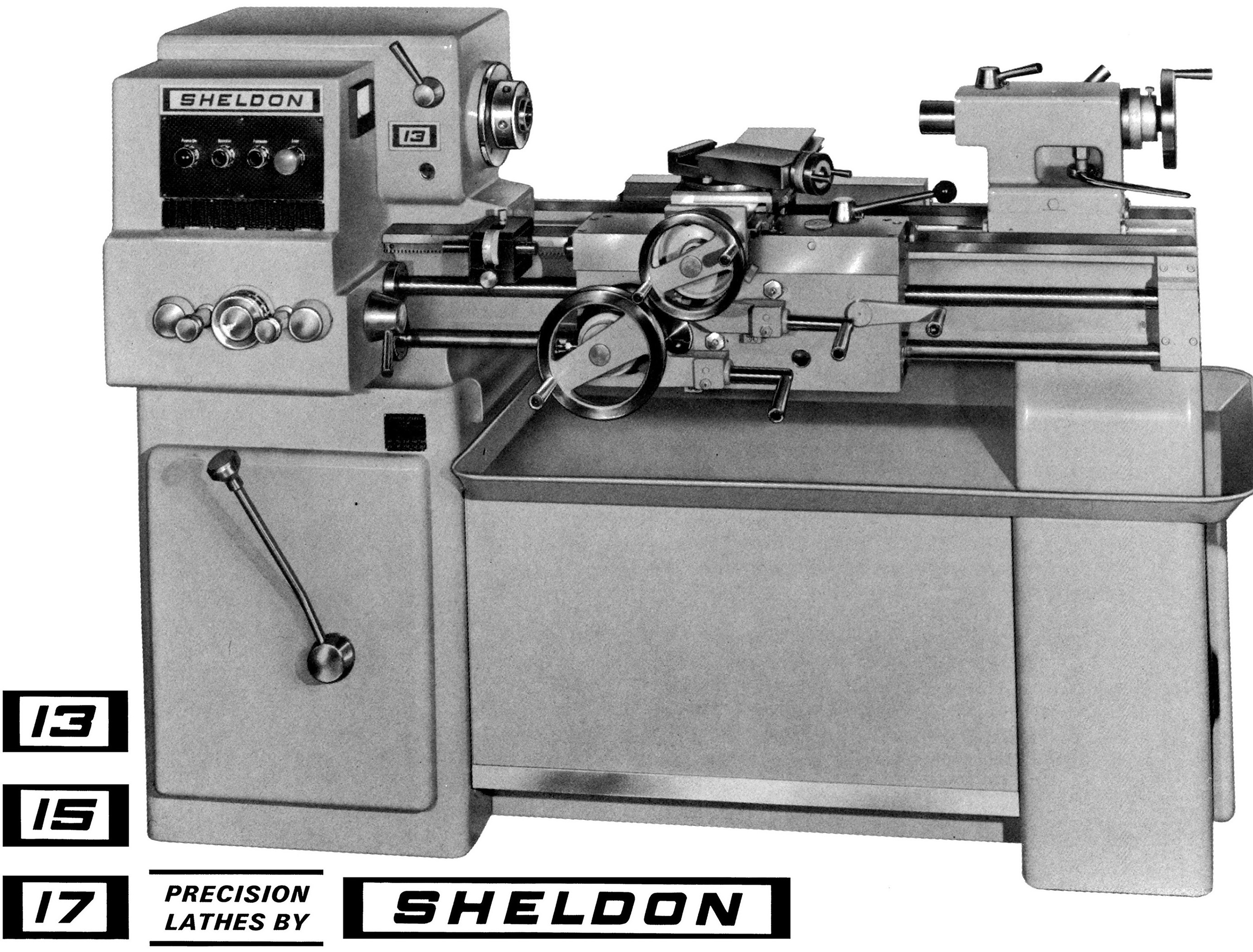
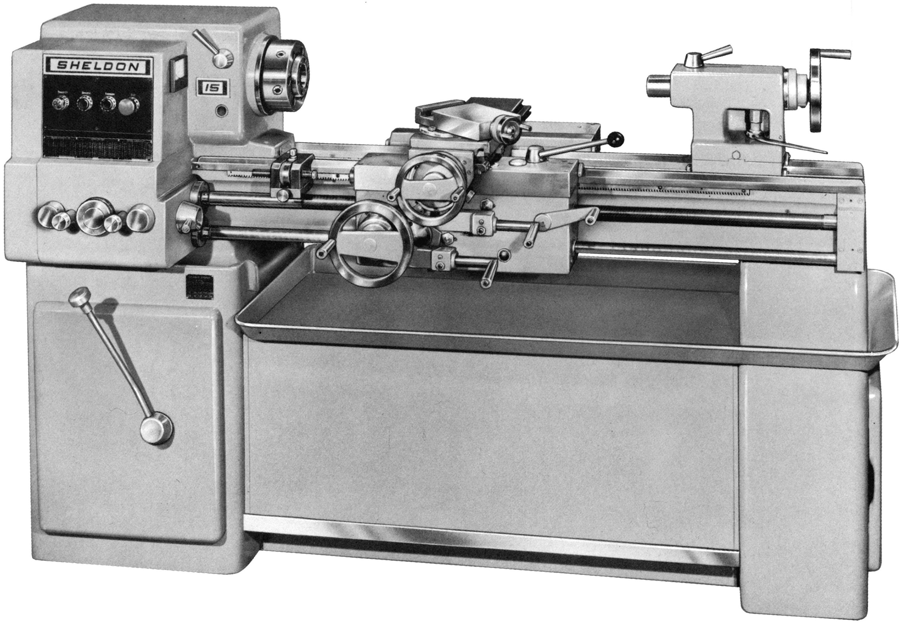
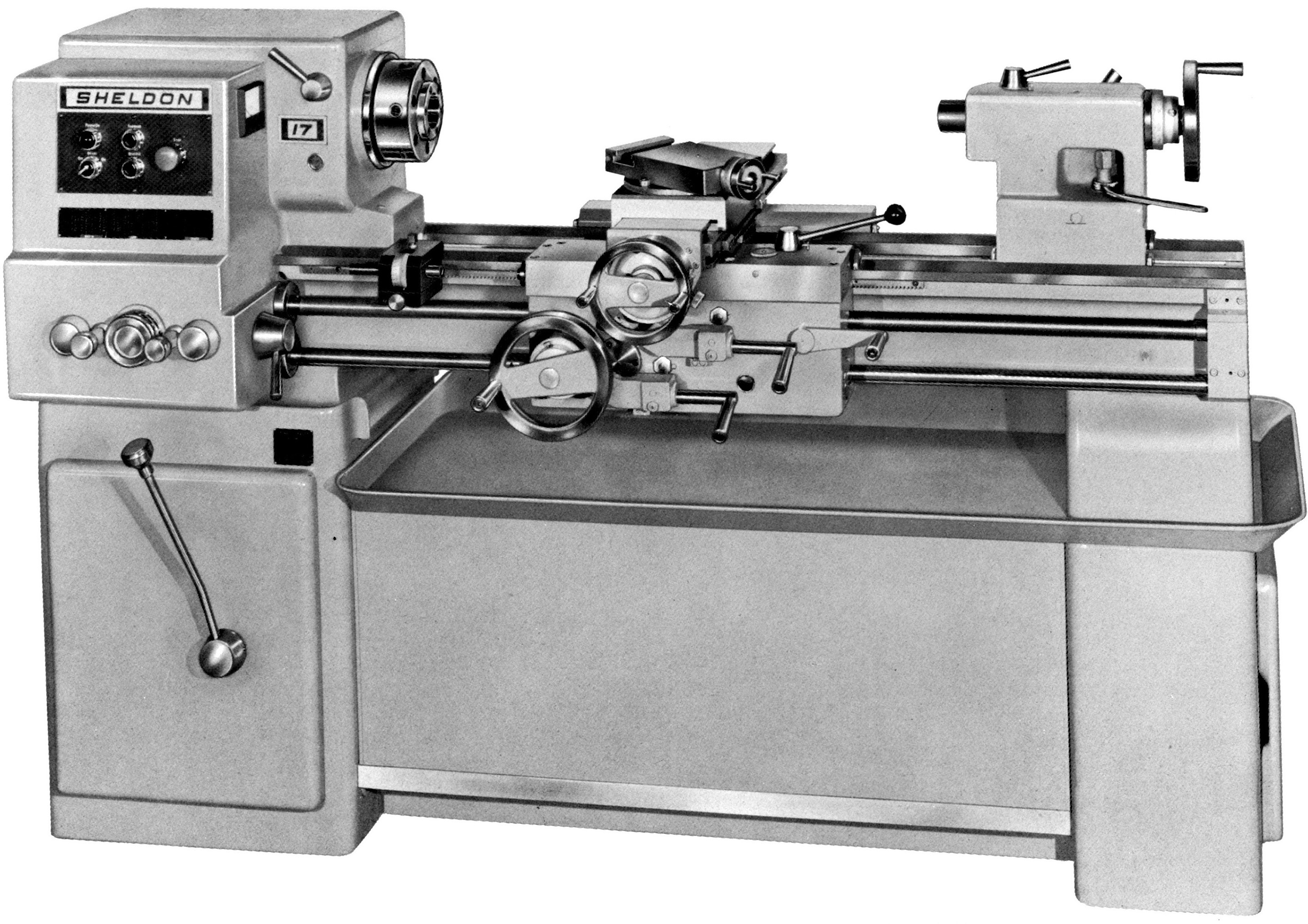
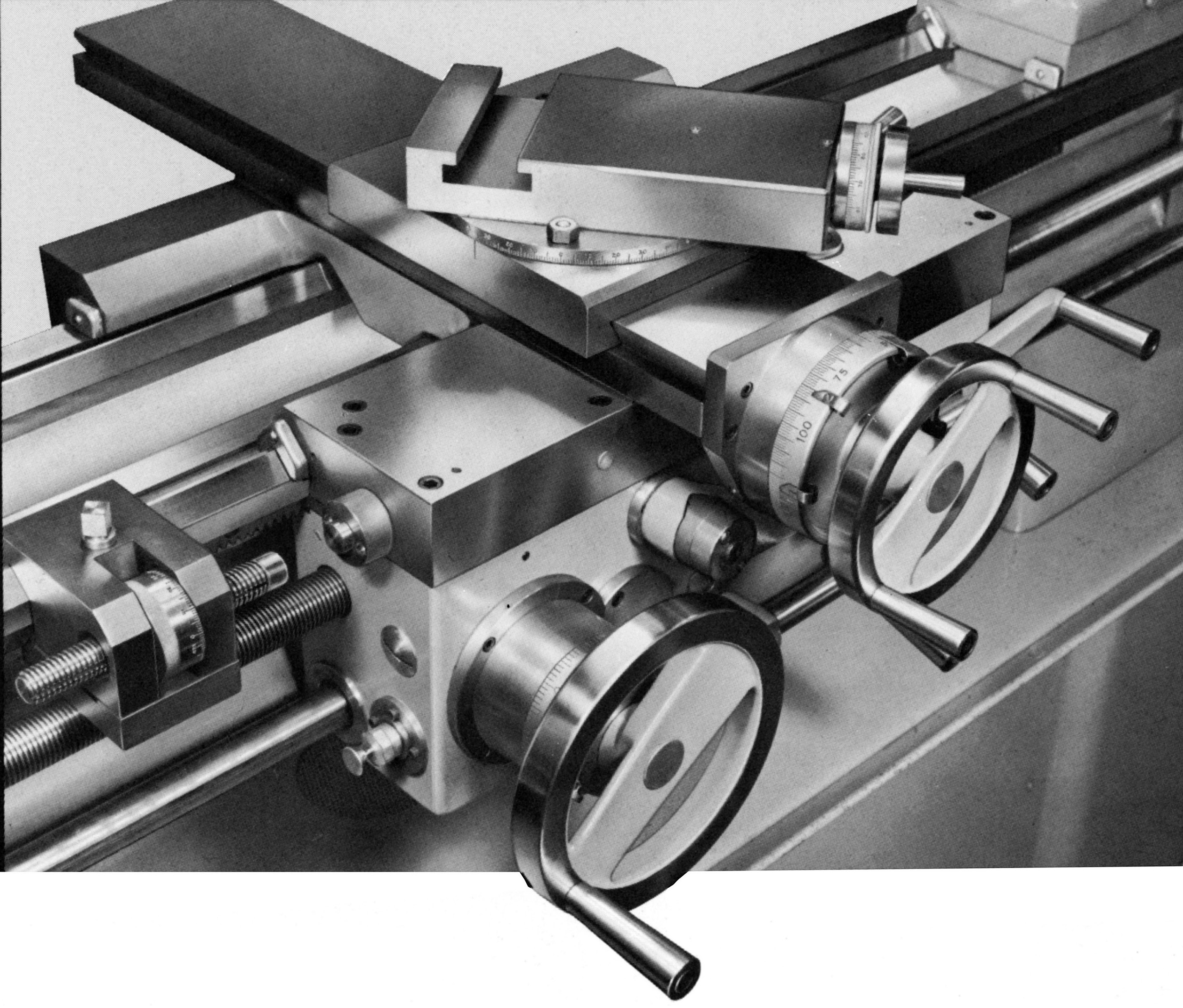
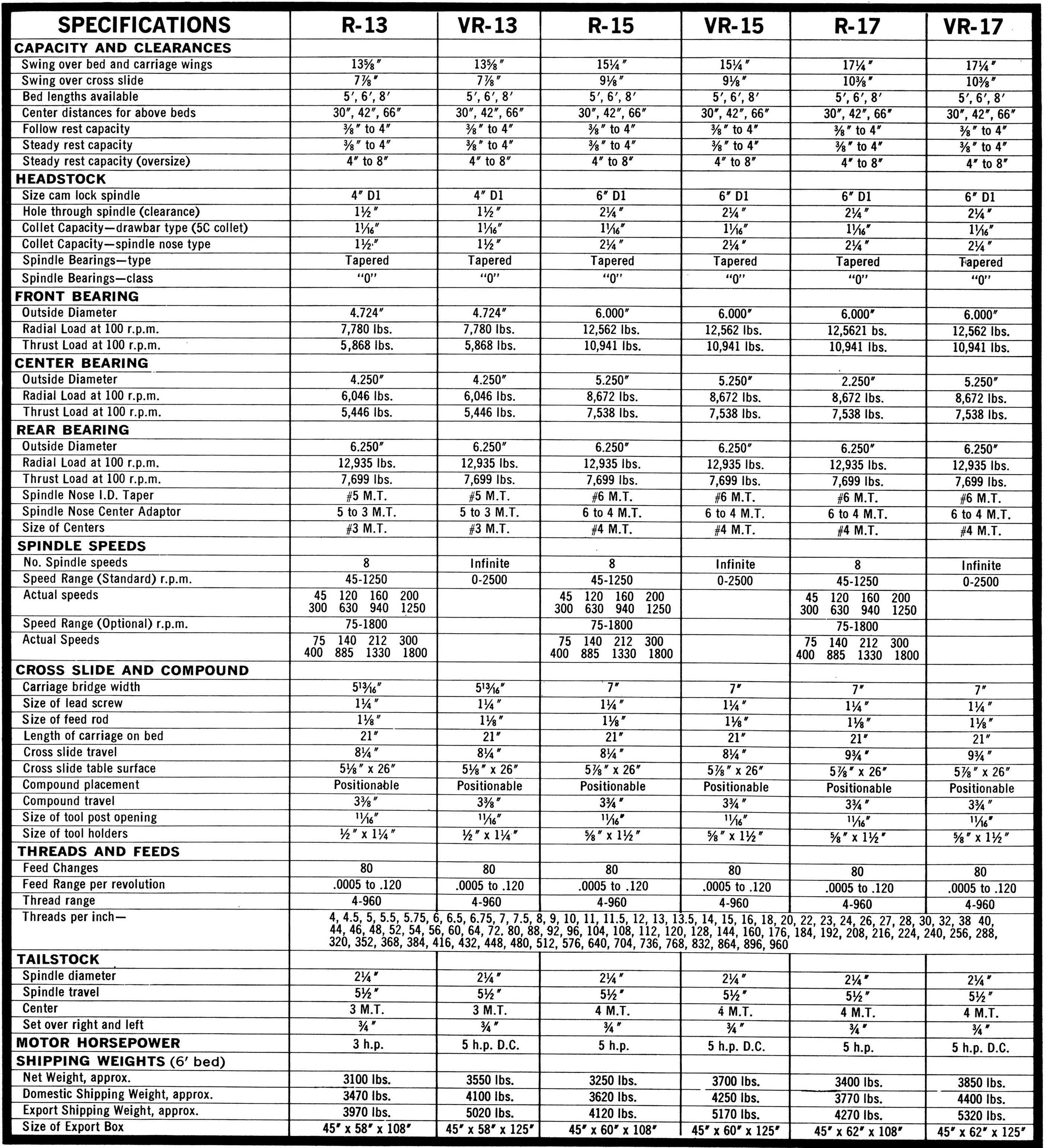
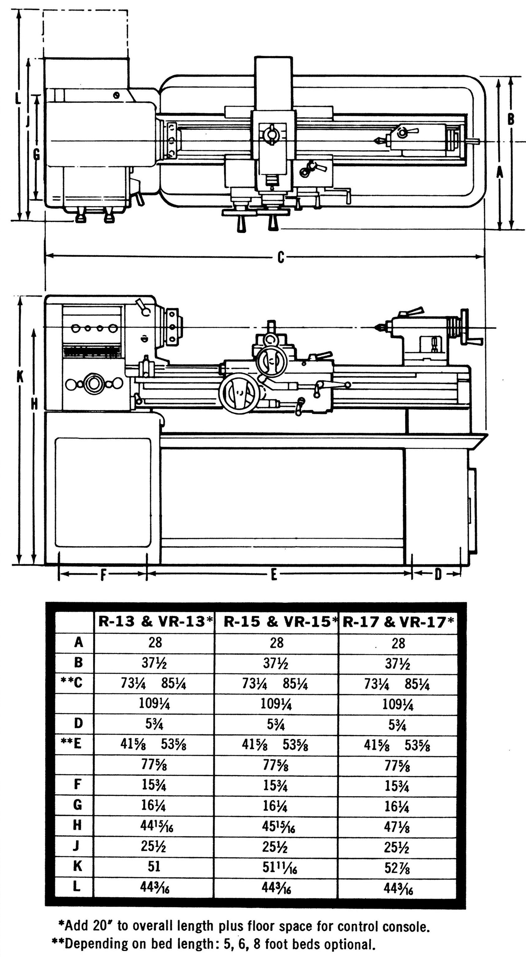
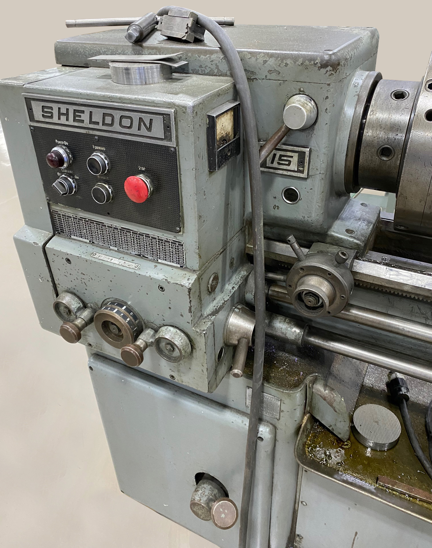
Based on the earlier 15-inch Sheldon - itself a development of even earlier machines - the new Sheldon lathes had been carefully designed to incorporate a range of significant improvements and could be had with between-centre capacities of 30, 42 and 66 inches. While the 13-inch model was more lightly built than the larger pair - these differing only in capacity - all shared a number of useful design details intended to help survival in an industrial environment. Beds were flame hardened, the cross-slide dovetails and ways hard-chrome plated, the top and cross-slide screws hardened (and the latter with an anti-backlash nut), one-shot lubrication to the bed, carriage and cross-slide ways and cross-feed nut, very useful automatic stops to both the power sliding and surfacing feeds - and a micrometer-equipped carriage stop as standard. Two cross-feed stops were provided as part of the standard equipment with others able to be fitted as required.
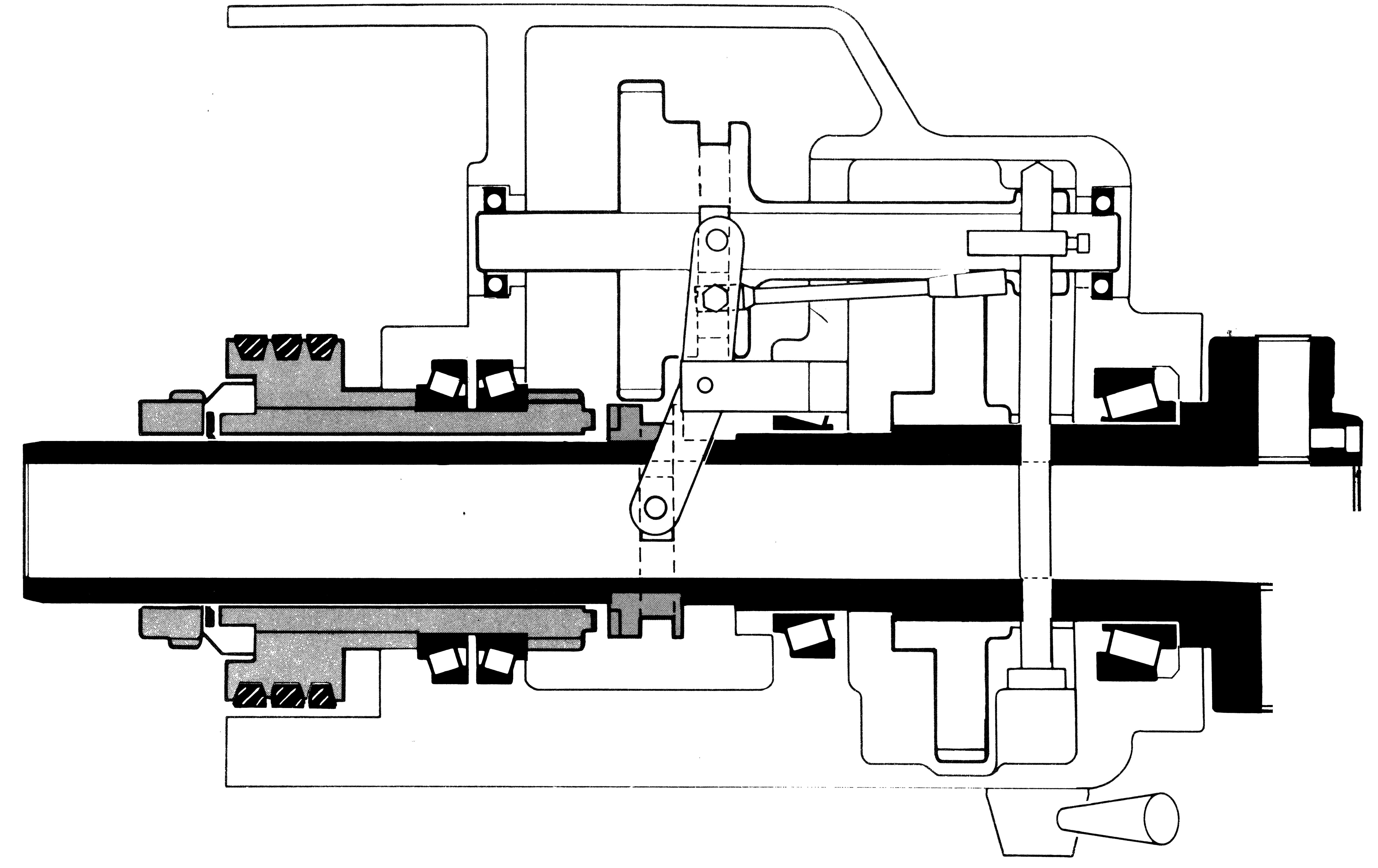
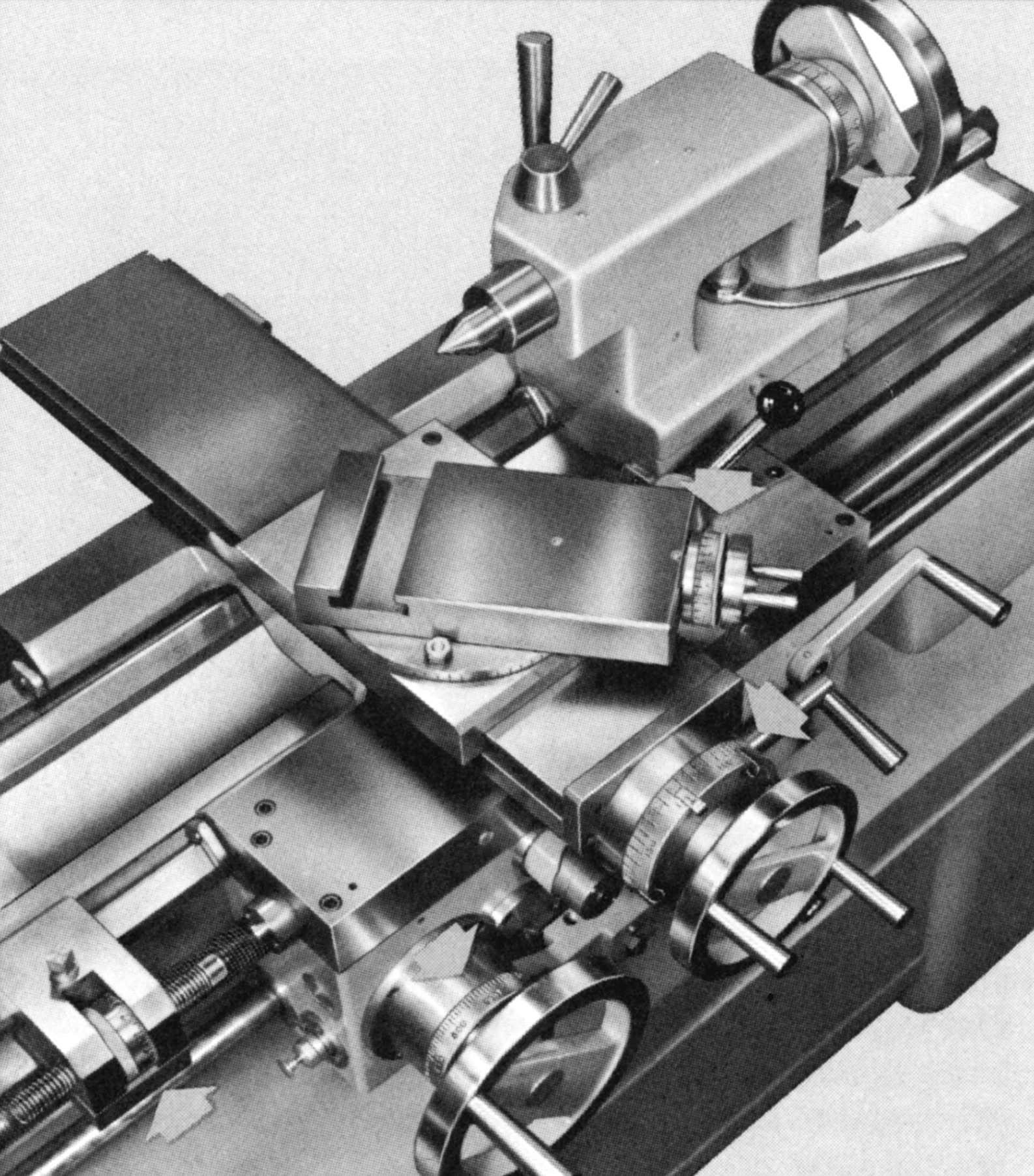
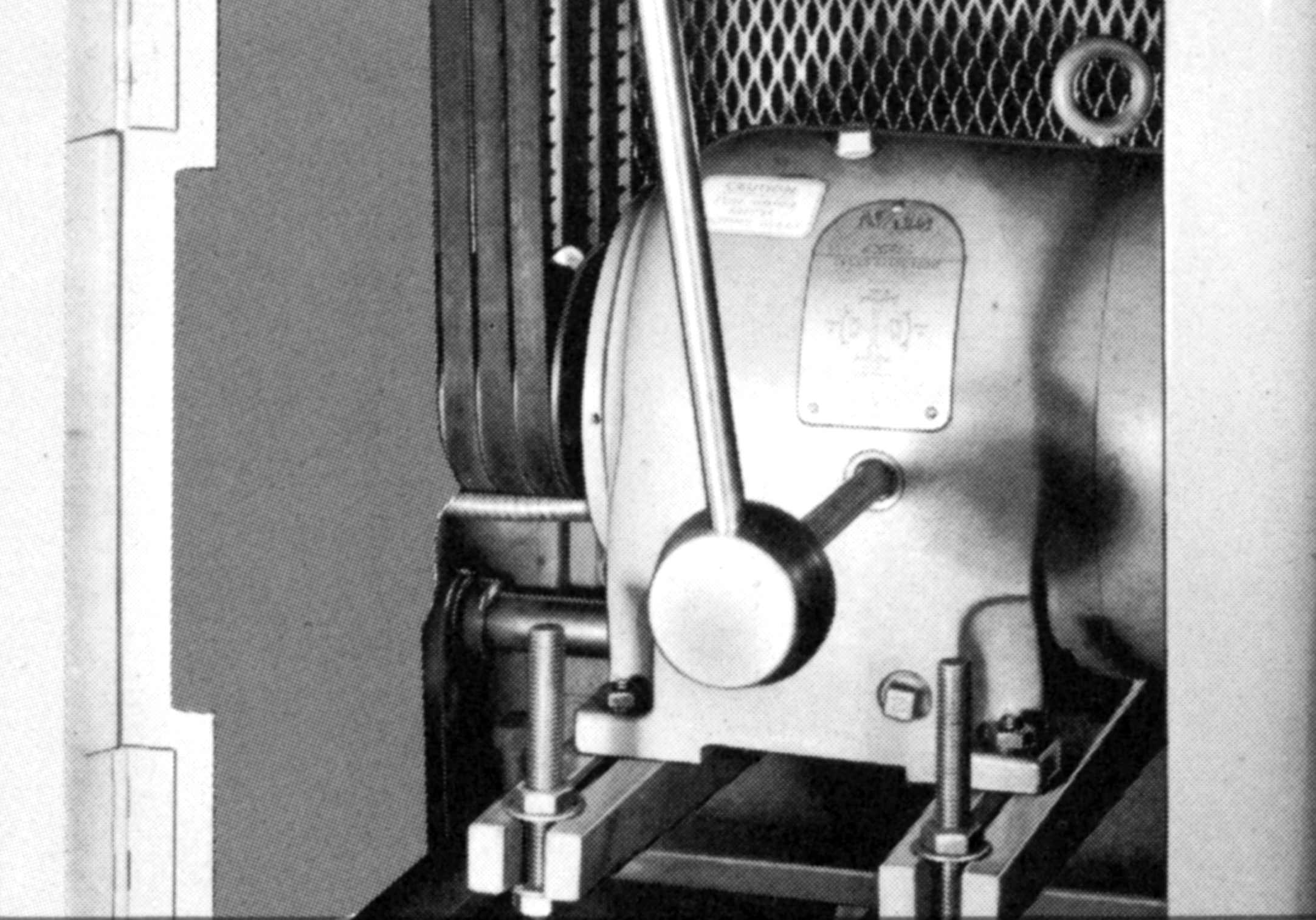
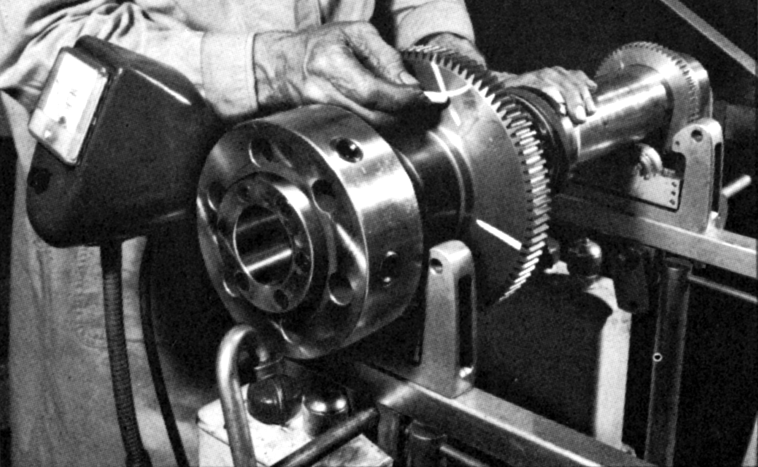
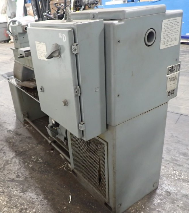
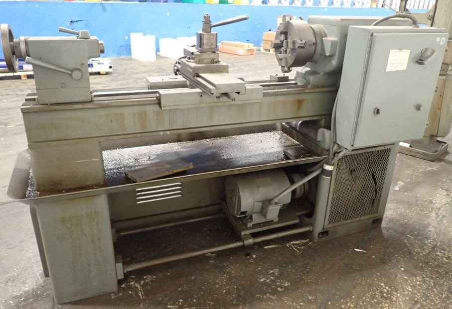
Similar to many lathes made in Europe( e.g. Voest, Dimco, Cardiff and Smart & Brown) the lathes used a drive system with a motor inside the cabinet base connected to a 4-speed gearbox. Final drive to the fully hardened and ground spindle (that ran in three "zero precision" taper roller bearings) was by three V-belts, the spindle pulley being overhung on the outside end of the spindle. The pulley drove the spindle though a "peg" and so was isolated from it, the aim of this arrangement being to stop gear chatter being transferred to the workpiece - though the headstock did contain low-speed backgears with the whole assembly running in an oil bath. On the R-13 the D1-4" spindle nose was formed with a 3 Morse taper and a bore of 1.5" - while R-15 and R-17 both had a D1-6" nose, a 6 Morse socket and a bore of 2.25".
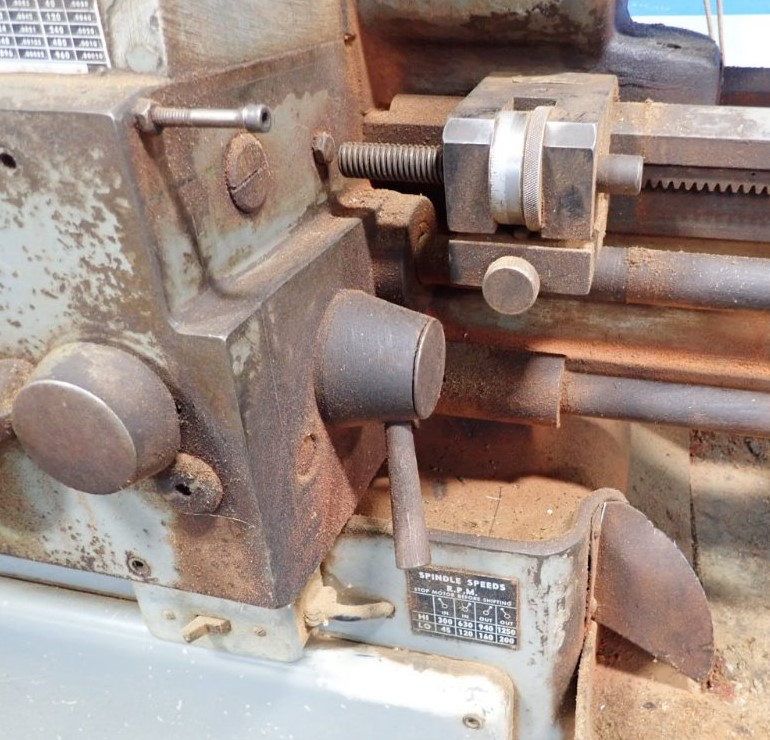
As standard, just a single-speed motor was fitted but, at extra cost, a 2-speed one could be fitted - as could ones with a brake. The R13 had a 3 h.p. motor while a 5 h.p. was used on the R-15 and R-17. Standard speeds, across the range, were 45, 120, 160, 200, 300, 630, 940 and 1250 r.p.m.; however it was also possible to order a faster set that spanned from 75 to 1800 r.p.m.
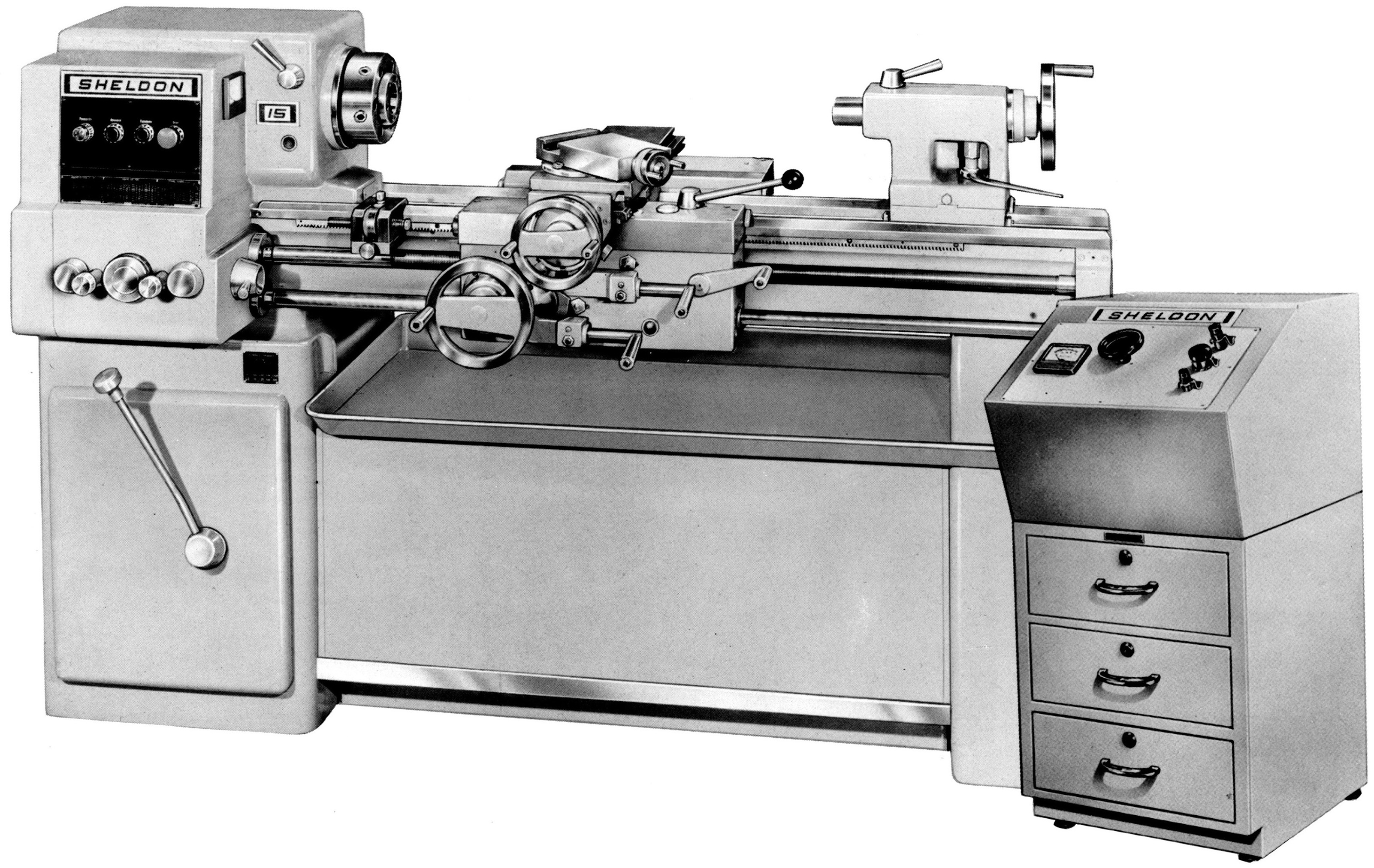
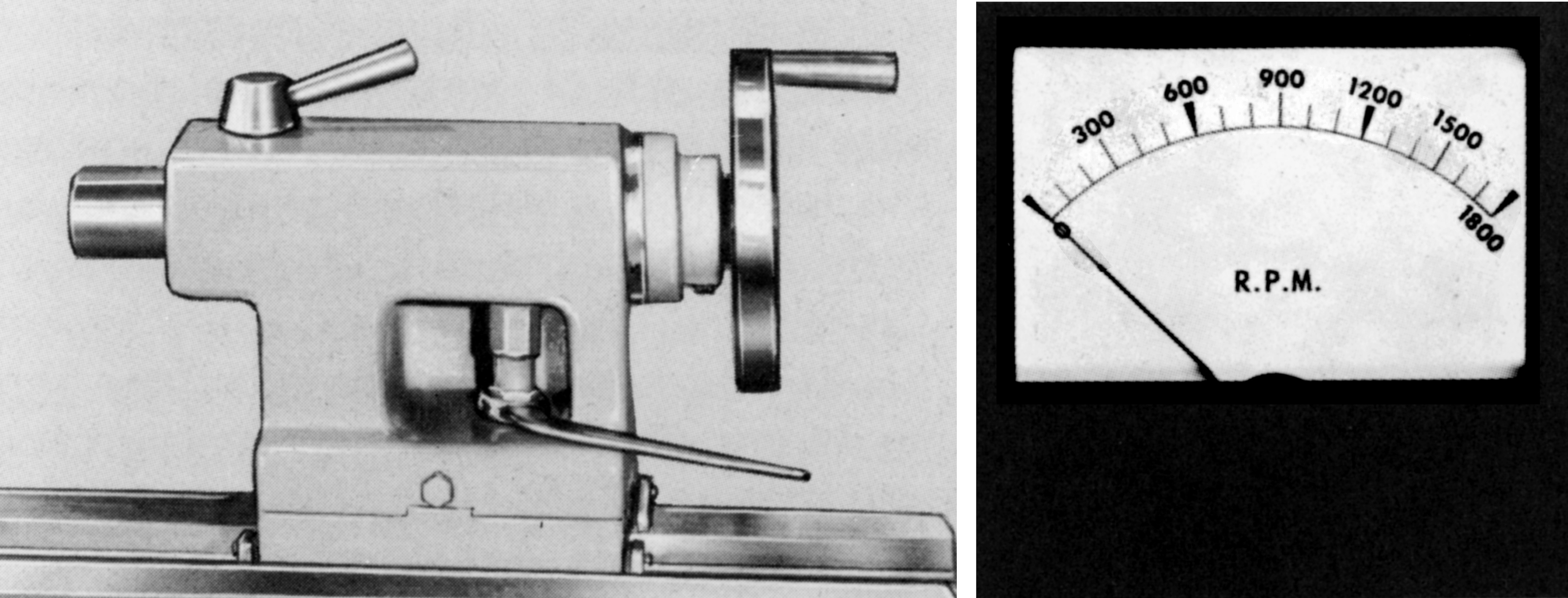
As a further option, another range of models was offered, the VR-Series, these being equipped with a high-precision spindle with a maximum run-out at the spindle nose of 0.0001". There was also a guarantee that the vertical and horizontal alignment of the headstock, measured at the end of a 12-long test bar was held within 0.0003". In place of the standard drive system, VR-Series lathes were equipped with an infinitely variable-speed drive that used a 5 h.p.. DC motor fitted with dynamic braking. These models aimed to provide not only higher accuracy but also, by the use of a series of 4-speed geared reductions, improved torque over the full range. Speeds were divided into eight ranges of 0 to 100 r.p.m, 0 to 230 r.p.m., 0 to 300 r.p.m., 0 to 400 r.p.m., 0 to 650 r.p.m., 0 to 1300 r.p.m., 0 to 1950 r.p.m. and 0 to 2500 r.p.m. A motor-load indicator was provided that showed the operator when to change to a different geared range would provide a more efficient rate of production. The motor control system was built into the top section of a 3-drawer tool-storage unit, a dial-operated potentiometer and electronic tachometer being provided alongside a set of push-button controls for spindle start, stop and reverse - these being duplicated across the front face of the headstock.
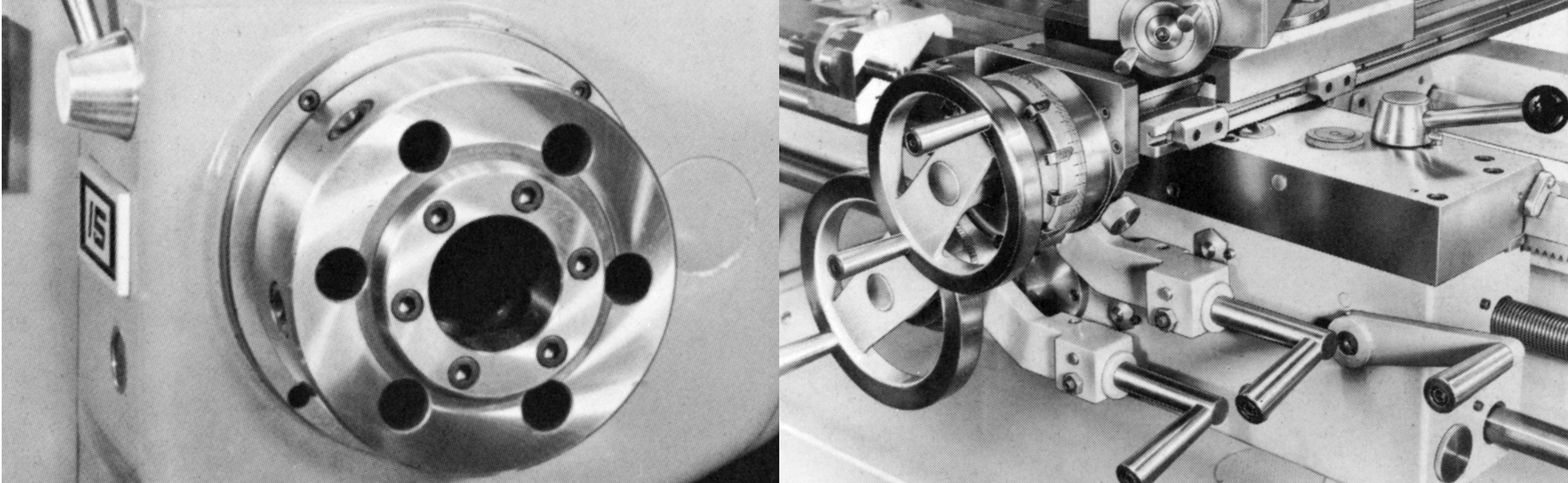
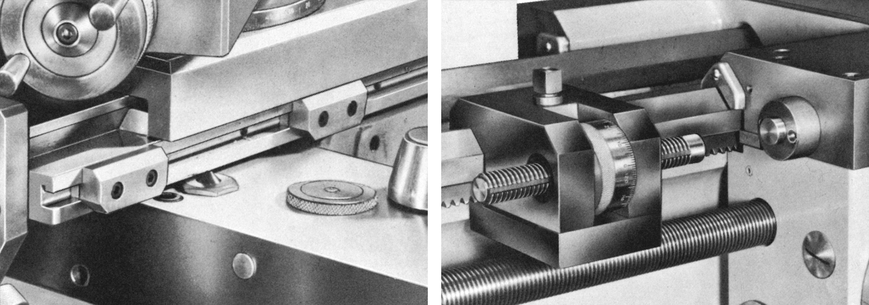
All models used the same screwcutting and feeds gearbox with an identical range of 80 different rates of feed from as slow as 0.0005" and 80 inch pitches from 4 to 960 t.p.i. The box was fully enclosed, oil-bath lubricated and operated by two knobs that could be revolved in both directions either individually or together. As the knobs were rotated, the feed rate and pitch appeared on a dial fitted between them. The box, which incorporated an instant-reverse control that could, very usefully, be operated with the box running, drove a leadscrew that was made from a stress-relieved steel and accurate to 0.0004" in any 4 inches and 0.001" per foot. .
Made as an enclosed box, the apron was fully enclosed, oil-bathe lubricated and two separate, lever-operated multi-disc clutches for the power sliding and surfacing feeds. The tension applied to each clutch could be adjusted from the front to provide a safety overload that could be varied according to the job at hand.
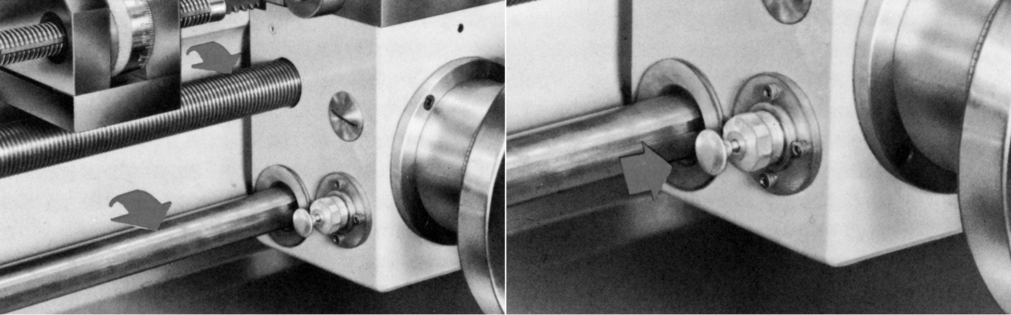
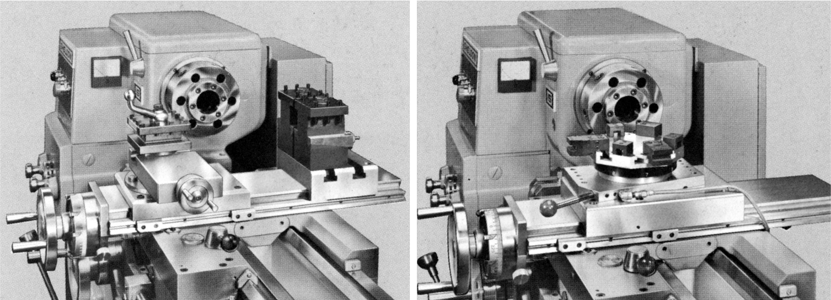
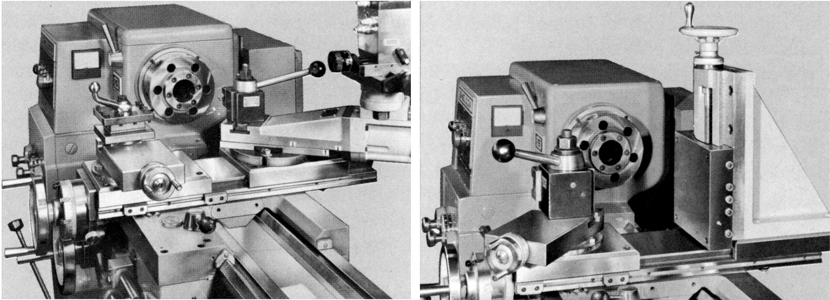
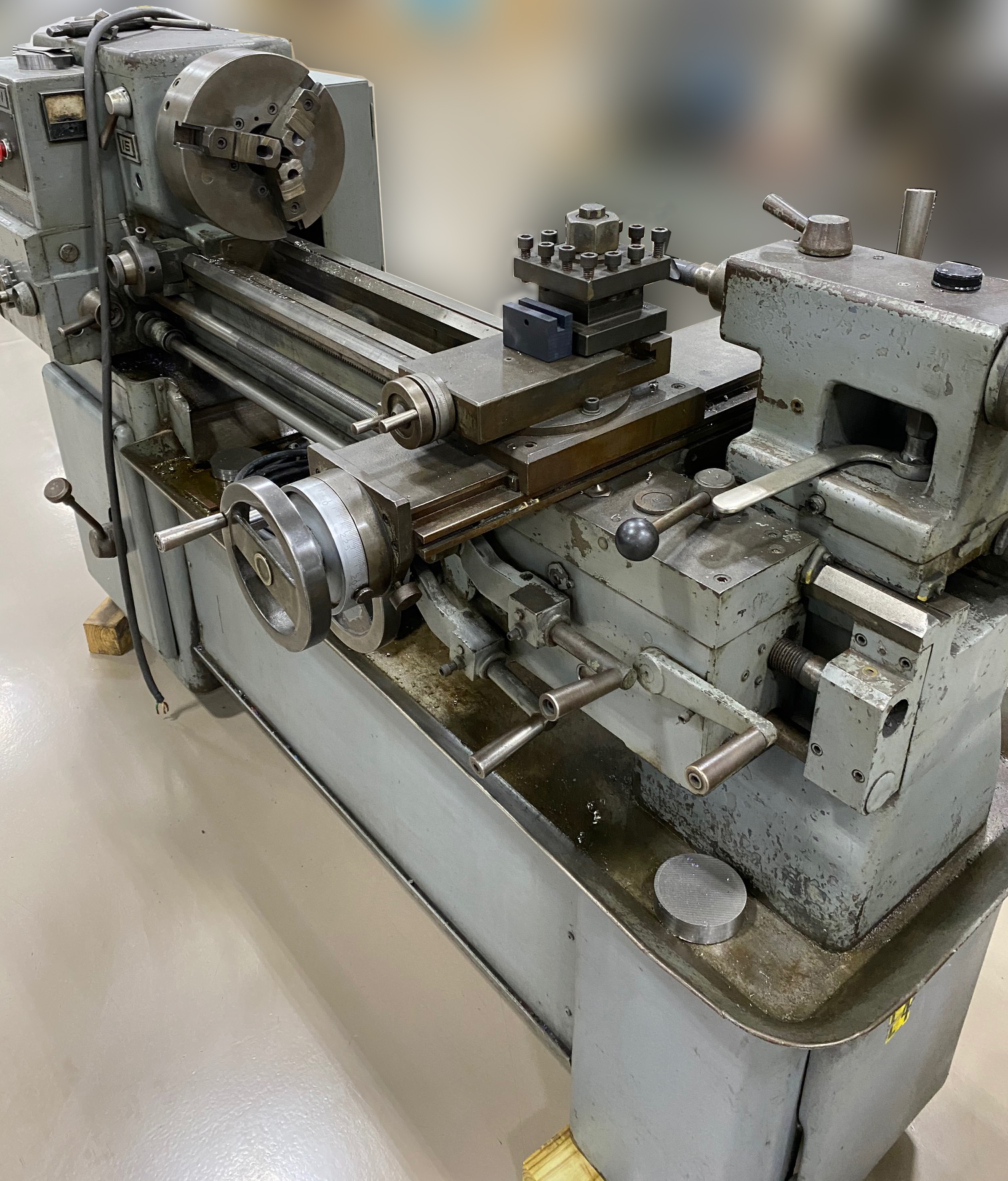
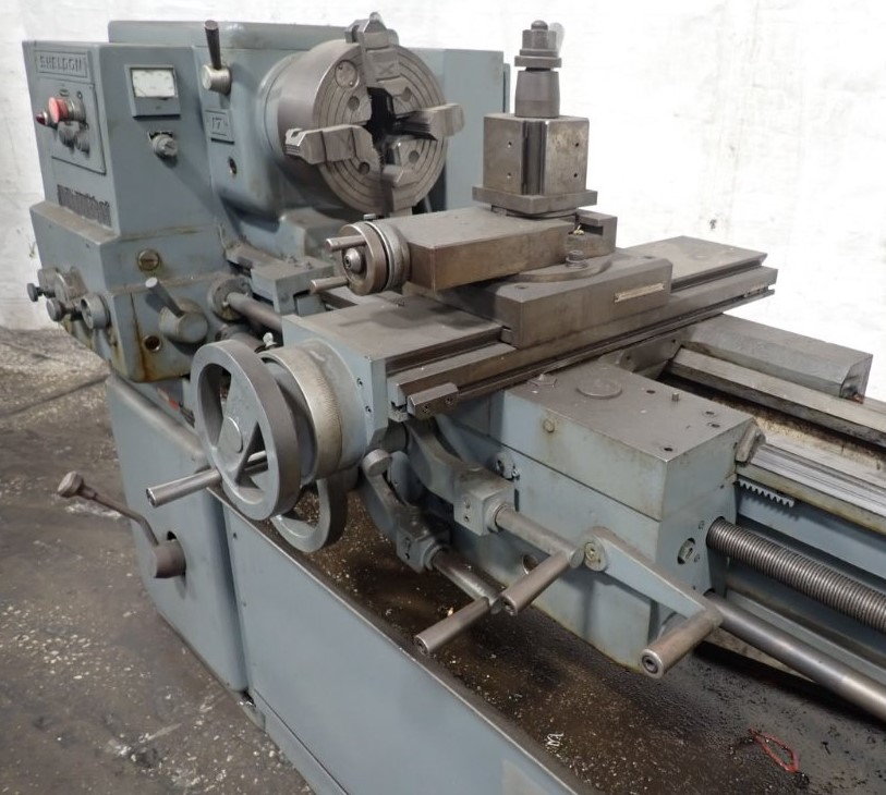
The saddle carried the compound slide rest assembly slightly offset to the left, with the bed's ways extending for a short distance in front of and behind the headstock. This arrangement allowed the cutting tool could be advanced right up to the spindle nose while still being fully supported. A possibly unique fitting was a built-in thread dial indicator that could be removed and stored in an apron cavity when not needed.
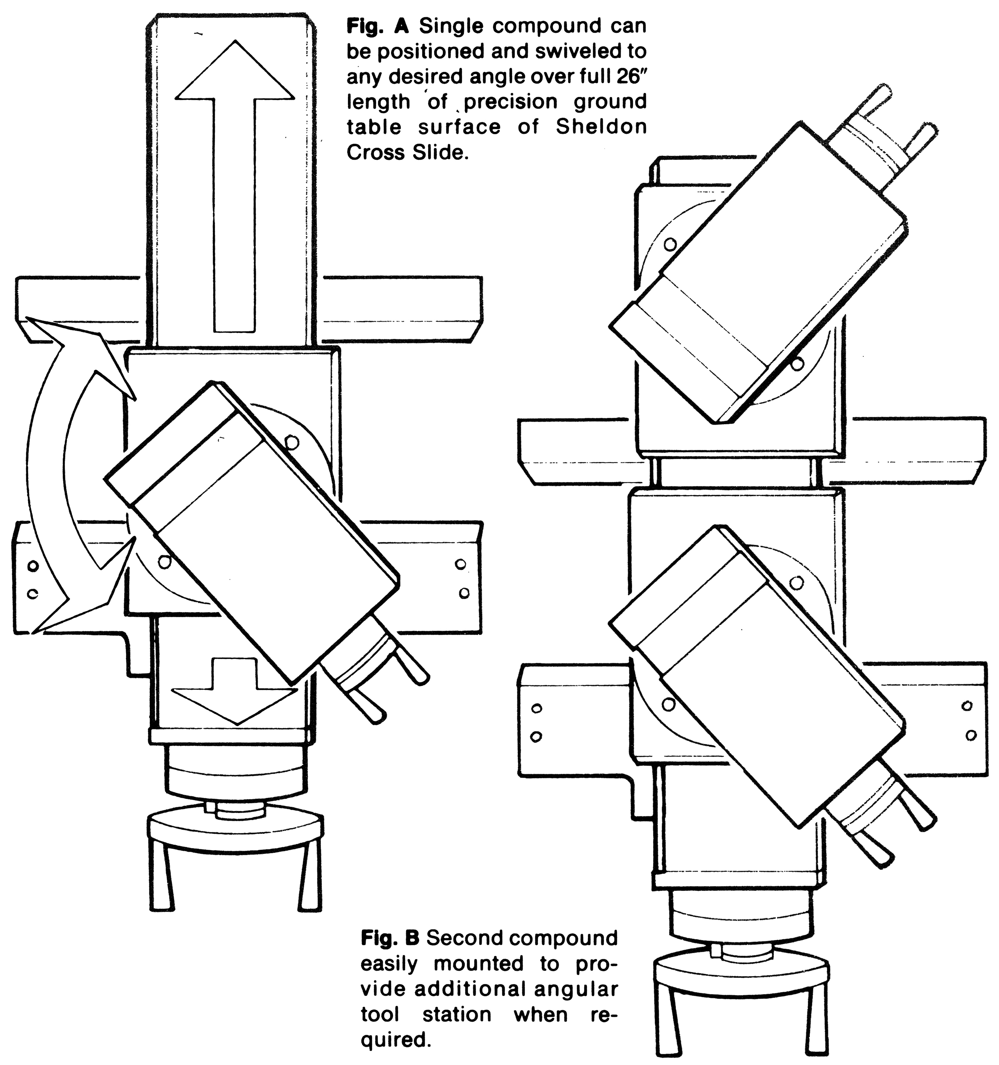
The cross-slide way was, on all versions an unusual 26 inches long and so able to mount both front and rear swivelling top slides, raiser blocks to carry rear-mounted parting-off tools, an 8-station capstan head, a hydraulically-driven tracer attachment and various "fixture plates" that included a form of milling slide. Cross-feed travel on the R-13 and R15 was 8.25 inches and on the R-17 9.75 inches. Top-slide travel was perhaps a little short being 3.375 inches on the R-13 and 3.72 inches on the R-15 and R-17..
|
|