email: tony@lathes.co.uk
Home   Machine Tool Archive   Machine-tools Sale & Wanted
Machine Tool Manuals   Catalogues   Belts   Books  Accessories

Tom Senior Machine Tools
Tom Senior M1 and Major Millers

M1 & Major Millers Home Page


Senior Millers Home Page   Senior Lathes   Senior Shapers & Planers  Firth Machine Tools  Price List

E Type   Junior Horizontal/Vertical   Light Vertical   VS   Major ELT   Tom Senior Older Millers

Instruction Books and Catalogues are available for the Senior range

If any reader has an immaculate Senior machine tool, the writer
would be delighted to feature it in the Archive

Parked on the left-hand side of the table is the maker's slotting head

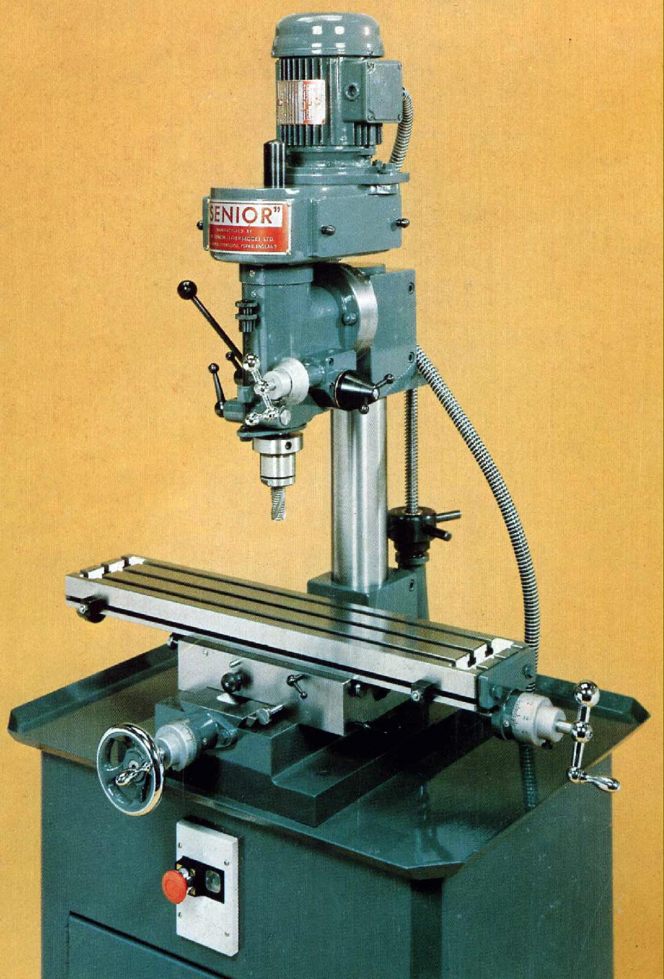
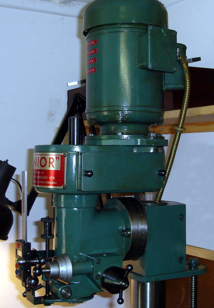
Senior M1 and major Millers invariably contain a "lathe-like backgear" assembly inside the main column. This useful mechanism enables them to be used to the limits of their strength and capacity in the horizontal mode - yet allows a usefully high range of speeds to be retained for the (simple type) of vertical head driven directly from the spindle nose.
A spring-retained pin in the face of the large bull wheel is drawn out to decouple the gear and pulley - and the lower gear slid along the shaft to engage it.

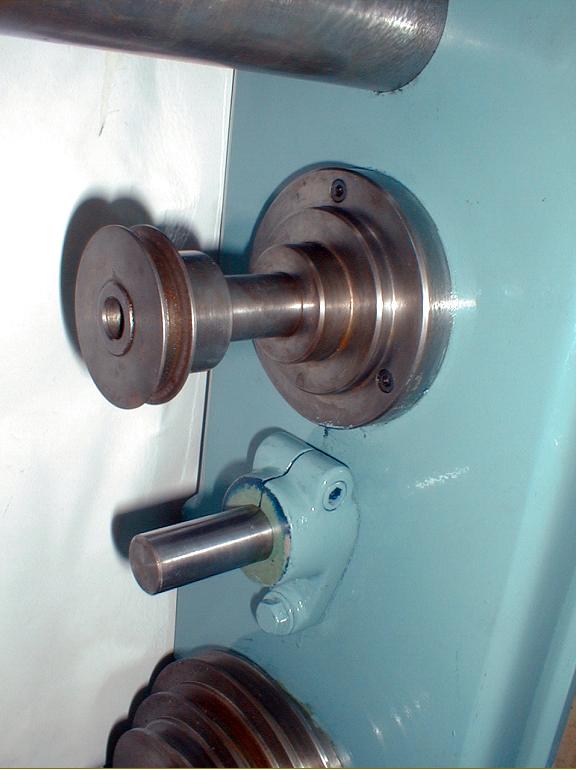
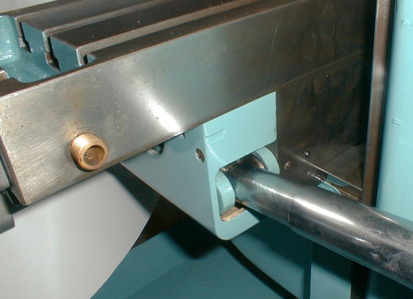
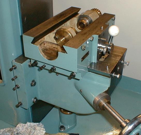
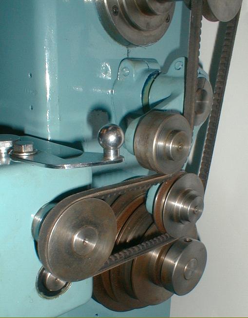
Power feed to the table is taken from a pulley mounted on the end of the main spindle. A Y-shaped arm functions both to tension the belt and keep the drive behind the main column where it can be safely contained inside the large, hinged rear cover.

Rear face of main column

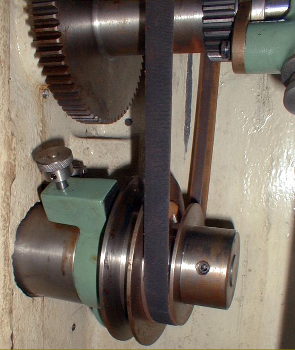
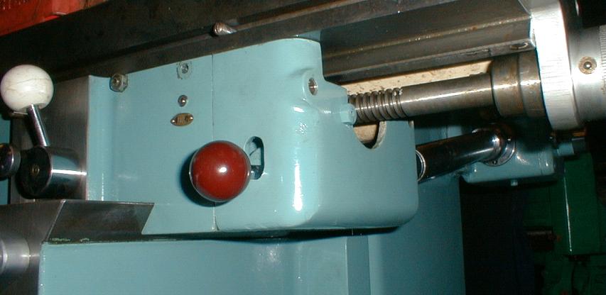
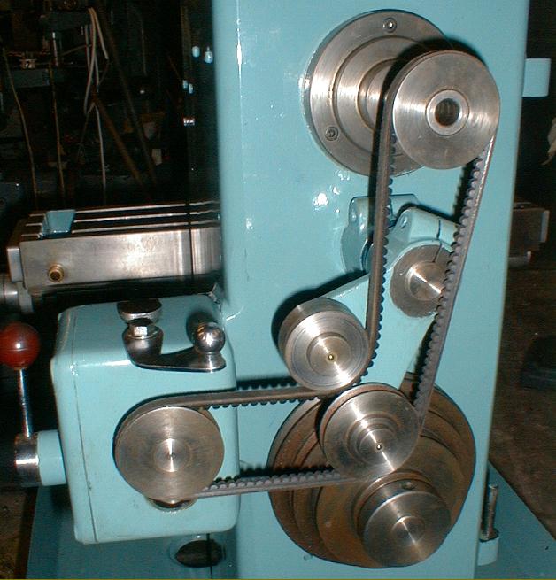
The lower pulley in the illustration receives power from the column-head mounted motor. It is mounted eccentrically and can (by pulling up the knurled knob) be rotating so that the belt tension is released.

3-speed, oil-bath, table-feed gearbox. The chrome clip on top is used to secure the large cast-aluminium rear cover.

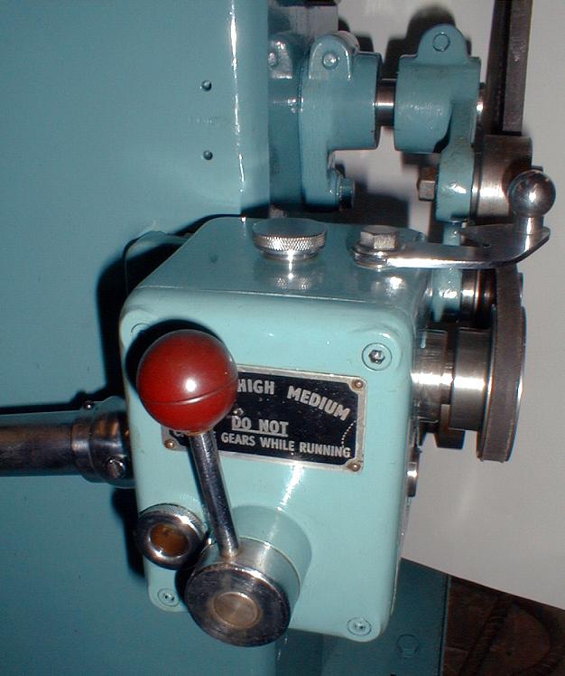
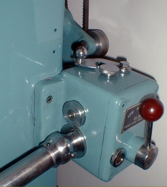
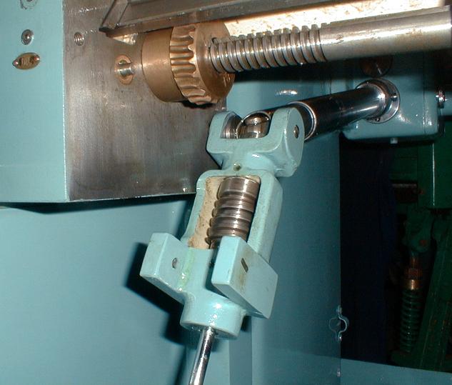
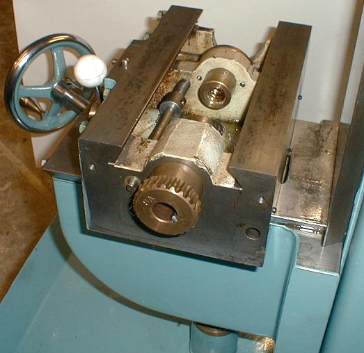
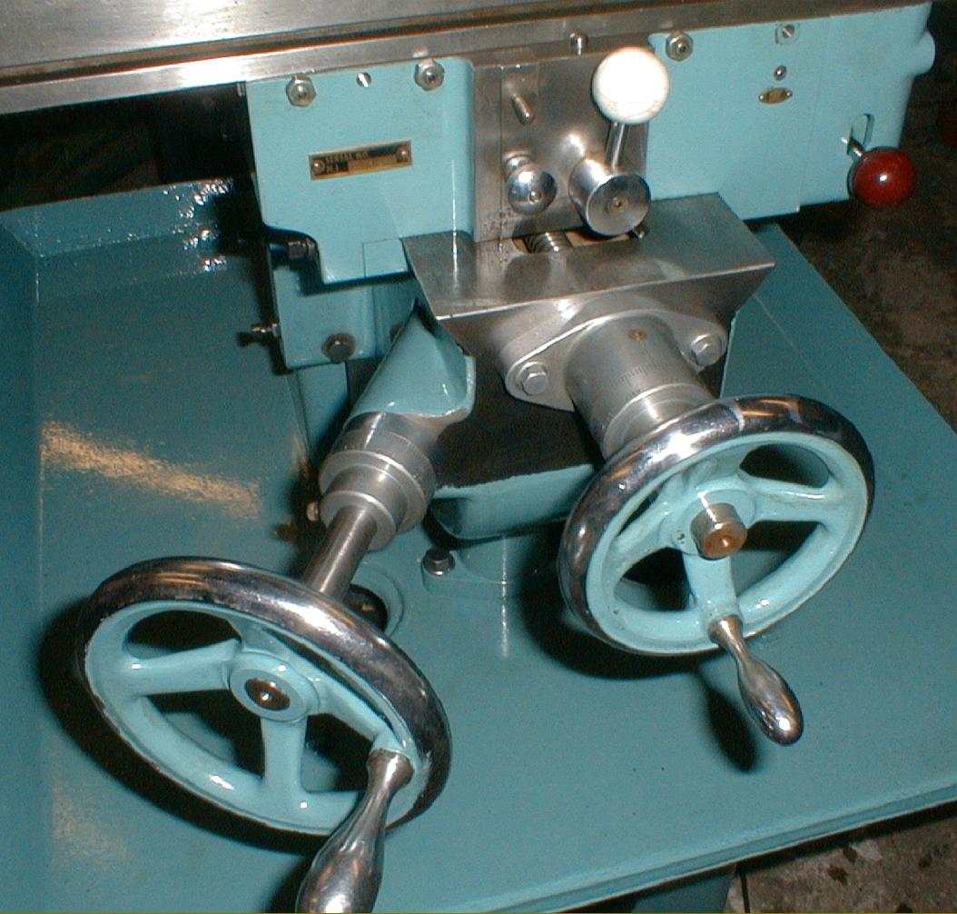
Worm box in the engaged position - the cover illustrated below is need to restrict its movement.

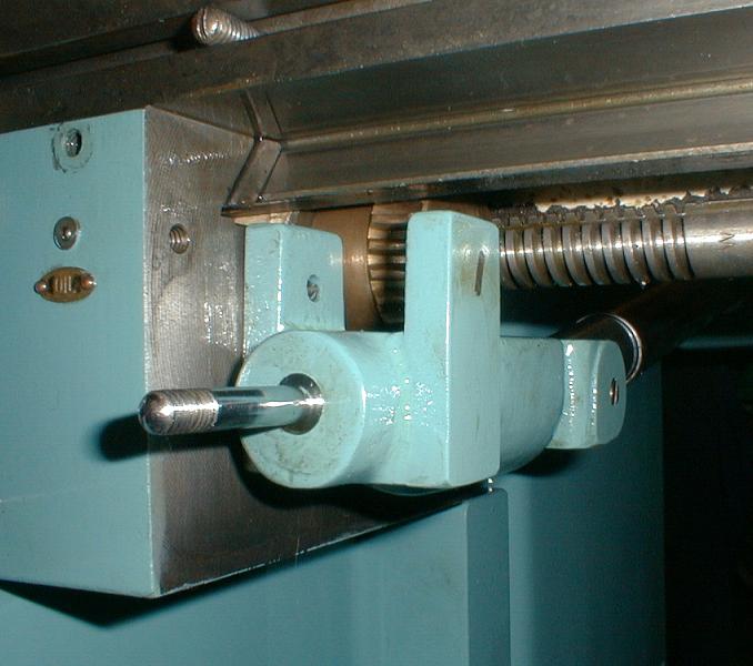
A bronze wheel on the table feed screw engages with a steel worm - contained within a housing which pivots on a pin in line with the universal joint.
The inner of the two arms on the worm box is retained by a spring-loaded pin which enables the gear to be engaged and disengaged from the wheel. The mechanism is prevented from dropping into the position illustrated by a cast aluminium cover - see below. The "exposed" gearing was used on early versions of the M1, later models used the arrangement on the Major where the worm-and-wheel gearing was provided with an oil bath.

The worm box is prevented from dropping out of engagement by simply letting its lever rest against the bottom of a slot cut in the cast-aluminium cover.

Rear view of the universally-joined table power-feed shaft. The shaft's sliding chrome covers safely guard the rotating parts.

Saddle with table removed - the trip bar for disengaging the power feeds lies along the left-hand side; its end protrudes through the wall of the saddle by the bronze power-feed gear.

Saddle with table removed showing the large bronze drive nut and power-feed gear and shaft.

The knee-elevating screw passed through a large bronze nut and mounted a crown wheel to engage with the pinion on the end of the knee-drive screw.

The knee and saddle assembly - complete with heavy, cast, chrome-plated handles and satin-chrome micrometer dials.

M1 & Major Millers Home Page

Instruction Books and Catalogues are available for the Senior range

Tom Senior Machine Tools
Tom Senior M1 and Major Millers

Senior Millers Home Page   Senior Lathes   Senior Shapers & Planers  Firth Machine Tools  Prices
E Type   Junior Horizontal/Vertical   Light Vertical   VS   Major ELT   Older Millers


If any reader has an immaculate Senior machine tool, the writer
would be delighted to feature it in the Archive

email: tony@lathes.co.uk
Home   Machine Tool Archive   Machine-tools Sale & Wanted
Machine Tool Manuals   Catalogues   Belts   Books  Accessories