email: tony@lathes.co.uk
Home   Machine Tool Archive   Machine-tools Sale & Wanted
Machine Tool Manuals   Catalogues   Belts   Books  Accessories

LeBlond Regal Lathes

Manual for the 10-inch Regal click here

Manual for the 1930s to 1940s Regal click here

Manual for the 1940s to 1950s Regal click here

Manual for the late 1950s onwards Regal click here


Regal Lathes 1930s to 1944  Regal Lathes 1944 to late 1950s
   
Regal Lathes late 1950s onwards  LeBlond Dual Drive
 
LeBlond Home   Regal 10-inch photographs


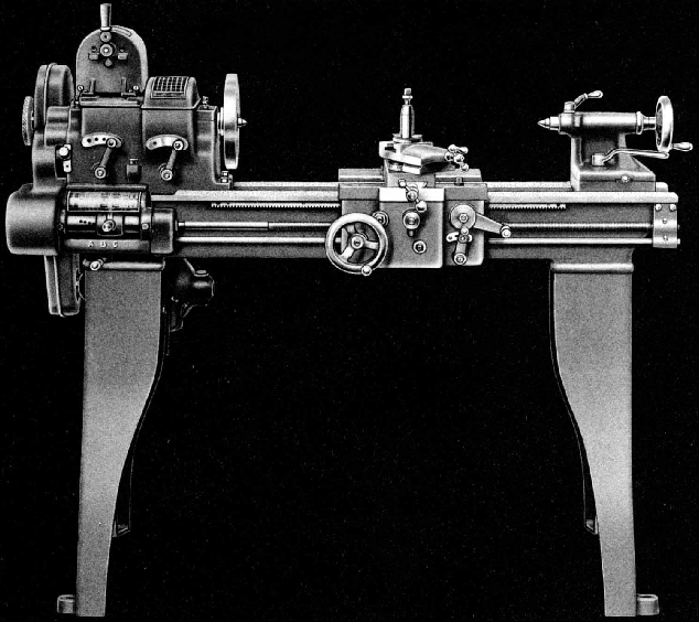
A very successful machine-tool manufacturer, the R. K. LeBlond Machine Tool Company of Cincinnati, Ohio had, since its founding in 1888, outlived five production plants, each in turn being replaced by a bigger and better-equipped facility. By 1929 their 440,000 square-foot factory, set in pleasant grounds at the corner of Madison and Edwards Roads, Hyde Park, was employing some 900 people, all devoted exclusively to the manufacture of heavy industrial lathes from ordinary "engine" types (backgeared and screwcutting to the UK reader) to massive, 60,000 pounds crankshaft-turning models equipped to finish all eight crankpins on an eight-cylinder engine at the rate of twenty cranks per hour. Whilst that might be considered a modest achievement set against 21st century machining times it was, for the era, a significant technical achievement and enabled LeBlond to offer state-of-the-art manufacturing equipment to automobile and other mass-production makers. Unfortunately, in 1930, LeBlond faced, as did all manufacturing industry, the Great Depression and its accompanying slump in trade. In order to survive, the company decided to widen its market and introduced, alongside it's long-established range of heavy engine lathes, a range of lighter, more-affordable models designed to appeal to the lower end of the market: better-off home-experimenters and model-makers, research departments, training schools, motor-repair garages, the self-employed and similar buyers. However, even with keen pricing and the backing of the respected LeBlond name, success could not be guaranteed for the new range, branded "Regal", entered a section of the industry already dominated by, amongst others, such well-established makers as South Bend, Sheldon, Barnes and Seneca Falls. Thankfully for the shareholders, LeBlond's approach was well thought out: although the lathes would only weight from one-third to one half as much, they would all mirror the quality and desirability of the company's industrial equivalents. They would have the most up-to-date specification possible, be easy to operate, come equipped ready for use and be introduced as a complete range with 10, 12, 14, 16 and 18-inch swings (actual capacity was always slightly more) Headstocks would be all-geared (no alternative flat or V-belt drive versions would be offered) with lever-operated speed changes and the exclusive use of built-on, self-contained motor drives with power transmitted to the headstock input shaft by the use of the recently-introduced (circa 1930) V-belt. All would have a proper screwcutting gearbox, a separate feed-rod to drive the sliding and surfacing feeds (engaged by a fool-proof, snap-engagement system) and a robust carriage assembly whose design was not compromised by having to allow for a gap bed. As the sole concession to hard times, the least expensive model, the superb and compact 10-inch, could be had to special order with a set of changewheels instead of the standard-fit screwcutting gearbox and without the power sliding and surfacing apron. Very popular in the UK during WW2 (and with many examples still in use in the 21st century) production of the 10-inch was to end as early as 1945 - though other models, constantly developed and refined, continued into the 1980s. Notable changes in design occurred in approximately 1944 and (in very much more radial form) during the late 1950s when an even wider variety of models and types was introduced (these lathes also being built by Sheraton in Australia as the Cub, Cadet (6.75" x 28") and Diploma (7.7" x 22") with the larger industrial models being called Challenger (7" x 35.5") and Defiance).   The two earlier types of regal are easily distinguished by the disposition of their headstock controls and the final model (in standard, Servo-shift and sliding-bed forms) by its modern, very angular lines. Although the larger Regal lathes in 21 and 24-inch sizes were enormous machines, comparable in some respects to the proper very heavy-duty LeBlond engine lathes, unfortunately there was an attempt to stretch them beyond their limits with the introduction of what amounted to very large-bore "Oil Country" headstocks.
In the 1980s LeBlond had tried to produce their lathes, particularly the lighter "Regal" models, all (or in part) at a low-cost plant in Singapore. This was the last gasp for the company and, when the new Japanese owners, Makino, had finished with them, they had built their last proper engine lathes. Unfortunately the patterns, core boxes, jigs and fixtures had all been shipped to Singapore and, when the end came, all were ordered to be burned or scrapped - a decision that precluded anyone from trying to resurrect the machines.
Continued below:


LeBlond Regal 10-inch

Continued:
Early Models
Made from close-grained iron mixed with steel and nickel the bed carried inverted "V" and flat ways (separate for carriage and tailstock) with the front and back walls in the form of I beam sections joined by closely-spaced cross girths. The beds were first rough machined and then seasoned for some months before being finished planed in batches and then hand scraped to a "master". Each saddle assembly was also scraped to its particular bed and then, with the apron fitted, the carriage rack located to the bed with screws and dowel pins. An enormous variety of bed lengths was available that gave between-centres' capacities of 18", 24", 30", 36" and 42" for the 10-inch, 12-inch and 14-inch models (with an additional 66-inch model for the 12-inch and 14-inch swing lathes only) whilst the 16-inch and 18-inch could be had with a capacity of 30", 42", 54", 78" and 102" - and 126" for the 18-inch model only.
On all sizes of "Regal" the headstock was of similar construction with a box-form casting, closed at the top (with a heavy iron cover), reinforced under the main spindle bearings and with an oil bath in the base to lubricate the gears by splash. LeBlond recommended: "a medium grade of machine or automobile oil" - though this would have been before the addition to motor oils of chemicals unfriendly to machine-tool components left standing unused for long periods. The spindle bearings, phosphor bronze but tinned with a layer of high-quality "babbit", were retained by heavy caps locked down by Allen-headed socket screws. The bearings were hand scraped to the spindle and (to keep out any particles from worn gears) lubricated from separate flip-top oilers fitted with felt filter pads. Although the very powerful LeBlond industrial engine lathes would have had their main headstock gears made from drop forgings, on the Regal line all were made instead from steel blanks. After the machining the bore, keyways, splines, sides and cutting of the teeth, each gear was burnished before being subjected to a hardening heat treatment process. Other than those on the main spindle, headstock gears ran on shafts spinning in plain phosphor bronze bearings fed with splash oil that had been collected in reservoirs and filtered through felt pads. The final drive gears were of helical form and provided not only an exceptionally quiet and smooth-running headstock when new but also when well worn and badly abused. 8 spindle speeds were provided with a high/low lever on the right of the headstock's front face and a four-speed selector to the left with both indexing through positions located by spring-loaded plungers. To aid speed changes (and engagement of tumble reverse) a polished-rim handwheel was formed as part of the headstock drive pulley and arranged to protrude through the cast-iron belt-run cover. By gently moving the wheel back and forth the operator was able to persuade the gears into mesh as he moved the headstock selector levers. Although rather small on early versions the wheel was later increased in size to almost the full diameter of the pulley.
On stand-mounted lathes the hinged motor-plate (adjustable for belt tension) was bolted to the back of the headstock-end leg and on bench machines to the rear of an extended headstock-end foot. Although underdrive systems with the motor inside a cabinet leg had been in production for some time the importance of this new system, with its deceptive neatness, simplicity and economy cannot be understated for it quickly became an industry standard, being copied by almost all other makers of similar machines. A further important point was the provision as standard of an electrical reversing switch, mounted in a convenient position on top of the headstock: when the lathe was delivered it could be put to work straight away and its position in the factory of workshop determined not by where a cumbersome countershaft could be mounted, or the line-shafting picked up, but where was most convenient and efficient.
Continued below:

Early Regal headstock with 2-lever control of spindle speeds


Continued:
In order to give maximum support to the cutting tool the saddle was fitted with four long, equal-length wings and the cross-slide (unfortunately of the short type that tended to wear just the front and middle part of its ways) arranged to sit on its exact centre line. This theoretically desirable state of affairs was permitted by both setting the front and back faces of the headstock inwards - and so allowing the saddle wings to run on past the spindle nose - and the absence of an gap in the bed, an undeniably useful feature but one that brings complications in its wake.
The apron of the 10", 12" and 14" models was of identical design and, although of single-sided construction, was heavily built, tongued on the ends to locate to the saddle, clamped by 4 bolts and incorporated proven features from the maker's larger engine lathes. The gears were all cut from the solid and mounted on good-sized studs that ran in long, wear resistant housings. To ensure as rigid an assembly as possible the apron was dowelled to the saddle and clamped by a recent invention, socket-headed Allen screws, whose clamping force was so much easier to exploit that the slot-headed screws used by so many other makers that had to be tightened by nothing more than a glorified screwdriver. The arrangements for power sliding and surfacing feeds were well though out, of robust simplicity, and known for a long and trouble-free life. A feed-rod, slotted to pick up a key carried inside a long sleeve held in a bearing on the inside face of the apron, emerged from the screwcutting gearbox. On the end of the sleeve was a small pinion that drove a large crown wheel on whose supporting shaft was cut a wide-faced pinion. The drive was made to pass from the wide pinion to either the cross-feed screw or the bed rack by means of a 3-position sliding gear the knurled head of which emerged through the face of the apron as a selector for the operator to manipulate. With the selector pushed in power sliding was achieved (up and down the bed) with it pulled fully out power cross feed was selected. Only in its middle position would it safely allow the leadscrew clasp nut to be closed for screwcutting. Whilst the push-pull button selected the appropriate feed direction for engagement and disengagement a separate lever with two spring-indexed positions was used that simply slide the pinion into and out of engagement with the crown wheel. Unlike the "safety" wind-in-and-out clutches used by some makers that required the operator to anticipate the disengage position and then unscrew a control knob to stop the feed on the LeBlond the action was instantaneous and absolutely safe. To prevent damage to the gears by, for example, running the carriage into the chuck, the feed-rod on the 10, 12 and 14-inch models was in two parts but connected at a socket where a cross drilling on the inner shaft held a powerful spring that pushed on a ball bearing at each end. The balls sat in shallow sockets drilled in the outer shaft and, under normal conditions, the two parts rotated as one. In the case of an overload the spring-loaded balls allowed the shafts to slip but, as soon as the stress was removed, the mechanism automatically reconnected the drive. On the 16 and 18-inch versions a simple shear pin was provided in the feed-rod drive, the excuse advanced being that the more experienced craftsman employed on such large lathes would be unlikely to make simple handling errors.
The apron of the larger Regal models was an exact duplicate of that used on the company's heavy-duty engine lathes. Of double-wall construction, made from a single casting and braced by cross ribs, LeBlond claimed that its patented design contained around 50% fewer parts than generally used by competing manufacturers and was thus far less likely to go wrong or suffer wear of small but critical components. The main drive gears were made from drop-forged steel and ran on hardened and ground shafts with the bed rack engagement gear (the rack pinion, a source of weakness on many lathes) being in chrome nickel alloy steel normalised and hardened. The same sort of large crown wheel was used but driven by either of two pinions, one at each side and selected by a lever on the apron face, which had the effect of causing the carriage to move left or right without having to reset the headstock-mounted tumble-reverse mechanism. In the centre of the assembly was a "spider clutch", a ring of fine teeth, used to engage and disengage the drive. Although of different internal design the apron used external controls that mirrored those on the smaller machines: there was a similar kind of in-out feed selector button and one easily-operated lever (connected to the spider clutch) to instantly start and stop the feeds - with no friction device to hamper the process.
Continued below:


Early Regal carriage assembly

Continued:
Of utterly conventional design the compound slide rest had (the usual failing at the time) rather small friction micrometer dials, gib strips adjusted by pusher screws and a "short" cross slide that tended to concentrate wear the front and middle part of its ways. The top slide was clamped down by two T-bolts with their heads held in a circular T-slot machined in the cross slide. The graduations to indicate the degree of swivel were on the inside front edge, and hence difficult to read, but its tool-holding T-slot was usefully-large.
On all sizes of the first Regal lathe the screwcutting arrangements were identical - with an output gear on the spindle driving through an externally-mounted tumble-reverse mechanism (a reverse plate in LeBlond terminology) with the gears in steel and running on hardened studs. Whilst it was not unusual for smaller lathes to have the tumble gears on overhung shafts (and continues so to this day) on larger machines, from many makers, they were generally fitted inside the headstock where, better supported and running in oil, they had a far easier time. After WW2 LeBlond redesigned the Regal headstock so this improvement was included and also removed the quadrant-arm mounted sliding gear (that provided a change between fine-feeds and screwcutting) and built that mechanism into the headstock as well. The later, improved headstocks are easily identifiable by a pair of small levers, set one above the other between the main spindle speed-change levers.
Shared by the 10", 12" and 14" Models, the same ingeniously-designed quick-change screwcutting and feeds gearbox was used and consisted of a separate unit bolted to the front of the bed. The 20-degree pressure angle gears were all in steel (though not hardened) and lubrication of the box depended upon the whim of the operator who had to swing aside a protective plate on the top and use an oil can to fill a small reservoir from which lubricant tricked down various holes to appropriate places. An eight-position, spring-plunger selector slid along a long cylinder and protruded from the face of the box. It carried a captive gear that was permanently meshed with a long gear on the inside of the cylinder and could also be engaged with any of eight feed gears on an intermediate shaft. A horizontal, three-position lever at the bottom of the box and provided three different ratios for each of the eight positions on the tumbler (giving twenty-four in total) whilst a two-position sliding gear on the gear train from the headstock (its head protruding through the gear guard) doubled the number of feeds and pitches to a total of forty-eight. Pitches varied from 2 to 112 t.p.i and feeds from 0.0025" to 0.144" per revolution of the spindle.  Whilst the drip-lubricated screwcutting and feeds box used on the larger models was of a similar appearance to that used on the smaller versions its internal design was more akin to those employed on the company's larger commercial lathes, a design so successful that the company was able to proudly claim that the number of gearbox repair parts requested over 25 years been "practically nothing". A four-position selector on the face of the box increased the total number of threads and feeds to 56. Pitches varied from 1.5 to 184 t.p.i and longitudinal feeds from 0.001" to 0.125" per revolution of the spindle.
Unlike many machine-tool manufactures, including South Send, who bought their leadscrews in from specialist makers LeBlond made their own from lengths of a high-carbon steel bought in as ground stock. The left-hand Acme-form thread was first roughed out on a thread milling machine and the leadscrew then rested for a time sufficient to relieve the strains of the initial machining. It was then finished by a "thread-chasing" process on a special lathe equipped with a precision leadscrew itself cut from a certified Master Leadscrew kept under temperature controlled conditions. The screw was mounted on the lathe between ground washers with the thrust arranged to be taken at the better-supported gearbox end when cutting right-hand threads. Like other parts of the various models the leadscrews were properly sized according to their duties: 8 t.p.i by ¾" diameter on the 10-inch model; 6 t.p.i. by 1" on the 12-inch and 14-inch and 4 t.p.i. by 13/16" on the 16-inch and 18-inch versions.
Continued below:

Apron as used on the first Regal 10, 12 and 14-inch models

Continued:
The tailstock was typical of LeBlond practice: hand-scraped to the bed and built so that the upper section could be off-set on the sole plate for the turning of shallow tapers, the casting was also carefully shaped so that when brought up along side the top slide the latter could still be operated when turning very short jobs between centres. The Morse-taper spindle was of high carbon steel, ground finished and marked with ruler graduations for drilling. It was driven by an Acme thread running though a bronze nut and locked by a substantial lever that closed down opposing clamps.
The company's move into a new product line at the beginning of the 1930s proved to be fully justified with the Regals remaining in production until the early 1960s when they were replaced by a range carrying the same name but of radically altered design and very angular, modern styling. Although during their long production run the lathes remained essentially the same, after WW2 the 10-inch dropped and the other models revised with 13", 15", 17", 19", 21" and 24" swings (an interesting machine introduced at the same time, though it shared nothing with the Regal, was the ingenious if complex Dual-Drive. During the 1940s a number of improvements were made to functionality and durability by including the use of heavier stands with cast-iron box plinths beneath headstock and tailstock and offering as extras, various features including higher speed ranges to take advantage of carbide-tipped tools, roller-bearing headstocks, gap beds, a one-shot lubrication system that oiled the apron internals and bed and cross-slide ways, the useful feed-rod safety coupling extended to the whole range (instead of just the smaller models) and headstock spindles fitted with a multi-disc clutch and brake unit operated by duplicated controls levers on apron and screwcutting gearbox.
Regal lathes were offered with the usual range of accessories - chucks, steadies, taper-turning attachments, toolpost grinders, micrometer carriage stops - as well as an unusual "Millerette" attachment. Built in three sizes the unit carried a T-slotted table on which was mounted a worm-and-wheel driven indexing unit that allowed, besides the usual milling operations, dividing work and the generation of spur and bevel gears, splines and slots.
Tony Griffiths


Apron used on the early 10, 12 and 14-inch models

Apron used on the early 10, 12 and 14-inch models


Early 10, 12 and 14-inch screwcutting gearbox

Inside the early 10, 12 and 14-inch screwcutting gearbox


Manual for the 10-inch Regal click here

Manual for the 1930s to 1940s Regal click here

Manual for the 1940s to 1950s Regal click here

Manual for the late 1950s onwards Regal click here


Regal Lathes 1930s to 1944  Regal Lathes 1944 to late 1950s
   
Regal Lathes late 1950s onwards  LeBlond Dual Drive
 
LeBlond Home   Regal 10-inch photographs

LeBlond Regal Lathes
email: tony@lathes.co.uk
Home   Machine Tool Archive   Machine-tools Sale & Wanted
Machine Tool Manuals   Catalogues   Belts   Books  Accessories