|
When investigating leads about the origins of the firms "Boley" and "Boley & Leinen", the following information came to light - through the good offices of one of the American personnel drafted in to help restart German industry at the end of the Second World war. He writes:
The basic story, regarding the two Esslingen firms, I got either from Gunther Leinen, the grandson of the founder, or from Fritz Carl Mahr, who was a good friend of Gunther's. I also knew the son (Gunther's father) who was owner and manager of the firm at the end of the war, when I had my first contact with Boley and Leinen - and with the firm of G.Boley.
F. Carl Mahr was the principal owner of the big measuring instrument firm of Carl Mahr and I was told that the manner by which Boley and Leinen got the Boley part of the name was a matter of acute embarrassment to the Leinen family. The founder of the firm, Gunther's grandfather, had been employed by G. Boley, and left them, initially, to manufacture the bench vise of his design (this vise was always marked "Leinen" - but with G. Boley also making an exact copy of this very popular item). My understanding is that Leinen was quite successful with the vise and decided to go into the watchmaker's lathe business in direct competition with G. Boley - an already well-established name. Supposedly, he searched the town directory and located a not particularly well-off widow named Boley and persuaded her to become a partner in his firm. His firm thus became "Boley & Leinen". This is really all that I know of the matter. It would, of course be very interesting to know what relation the widow's husband had been to the G. Boley of the pioneer lathe firm. Unfortunately 1 have more or less lost touch with Carl Mahr and everyone else in the Esslingen region.
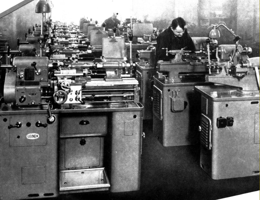
Over many decades Leinen were involved in the production of high-class machine tools including watchmakers' lathes and accessories, special equipment for the watch, instrument and scientific trades, precision plain-turning and backgeared screwcutting lathes, regular and special lathes for low-volume production work and a number of interesting milling machines including a version of the original Wolf Jahn type, a superb Micro miller/driller and an early precision bench drill
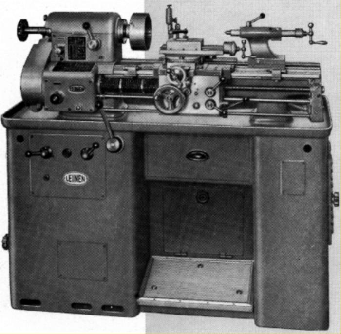
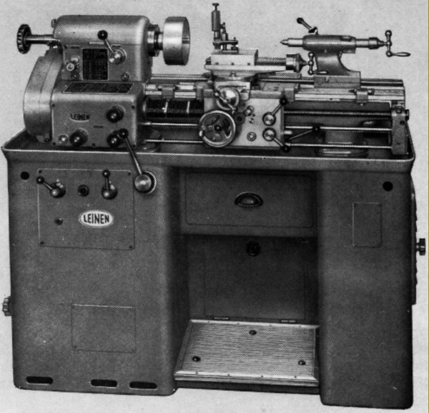
Leinen MLZ4S, LZ4S and LZ4P 5.1" x 19.7" circa 1950s
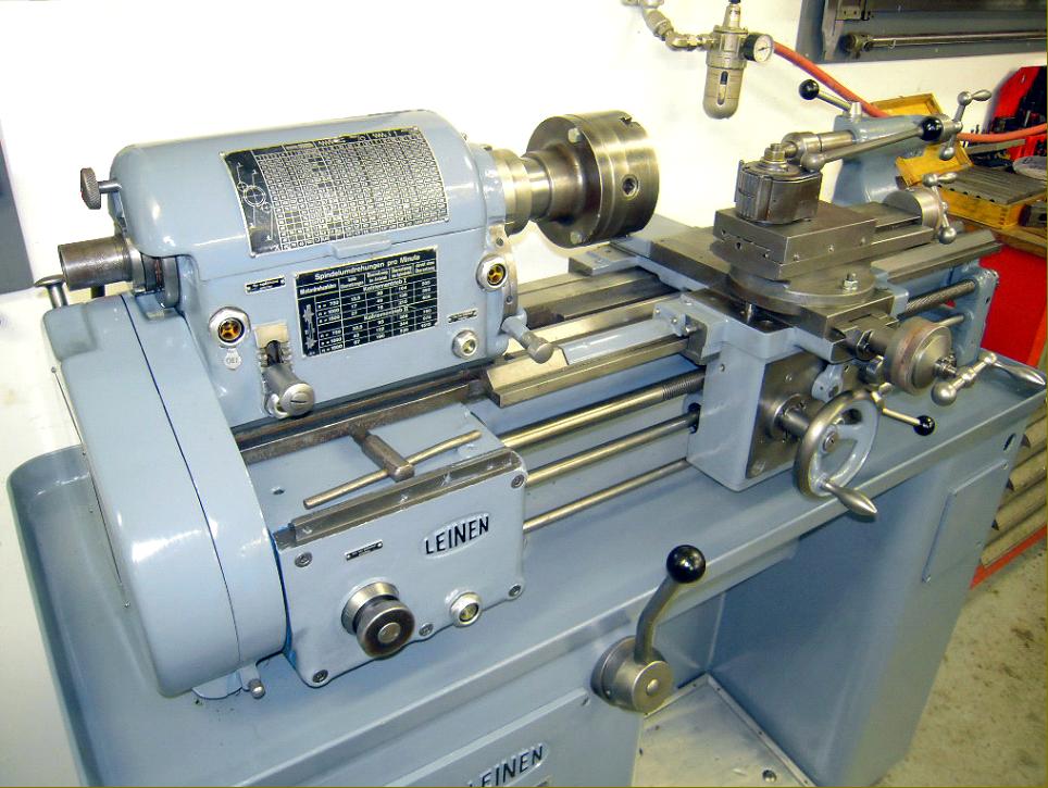
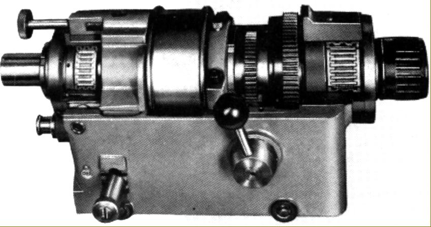
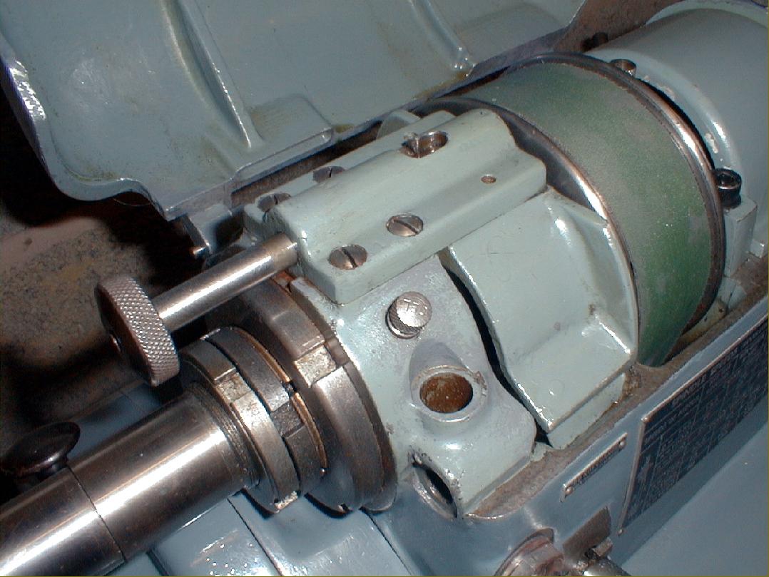
With pre-WW2 origins as the Model L4Z and LZ43, by the 1950s three versions of this very serious-quality toolroom lathe were available, the MLZ4S, LZ4S and the cheaper but less-common screwcutting-by-changewheels LZ4P. By the 1960s, although these lathes were commonly advertised with the maker's name "Boley Leinen", each model had the word "Leinen" before its type descriptor. The MLZ4S was fitted with a "Multiplicator" screwcutting gearbox where, by rotating three knobs (or levers on earlier examples) 27 different metric screwcutting pitches from 0.1 to 6 mm were produced as well as 35 longitudinal feeds from 0.017 to 1.16 mm per rev.). Two less expensive models that used changewheels for screwcutting, the LZ4S and LZ4P were fitted with a simple feed box to give six sliding and surfacing feeds for each setting of the changewheels and to direct the drive to the leadscrew or power-feed shaft. For lathes not intended for screwcutting (or to give an especially fine rate of feed on the screwcutting models) a two-stage belt drive could be fitted to power the feeds' box. On both machines the spindle bore was 0.98 inches with the spindle drive pulley (a very wide one to take a smooth-running flat belt) arranged, as on all similar high-class lathes, to run in its own bearings and to drive the spindle through a peg; the system so removing any chance of the drive belt's pull transmitting vibration or spoiling the machine's accuracy or upsetting the surface finish of a job.
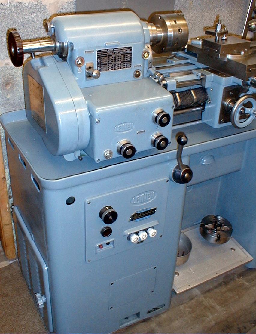
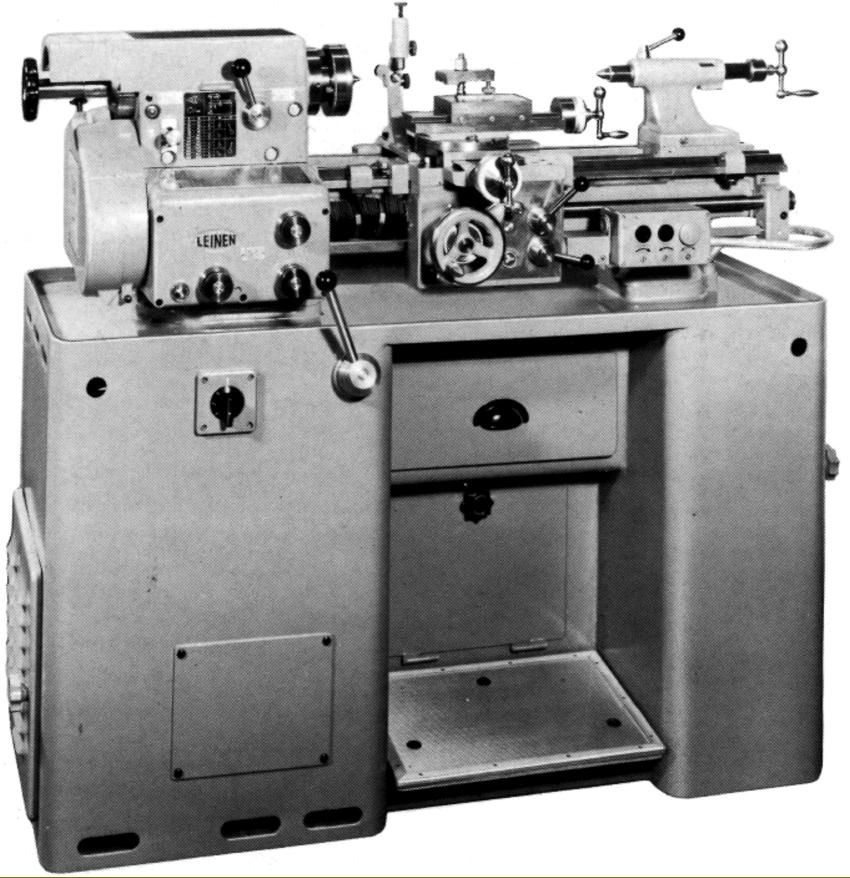
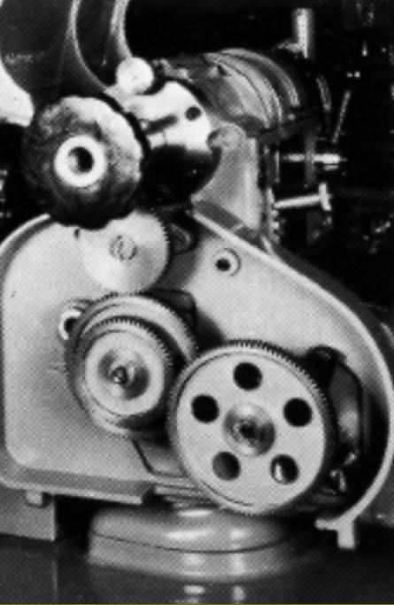
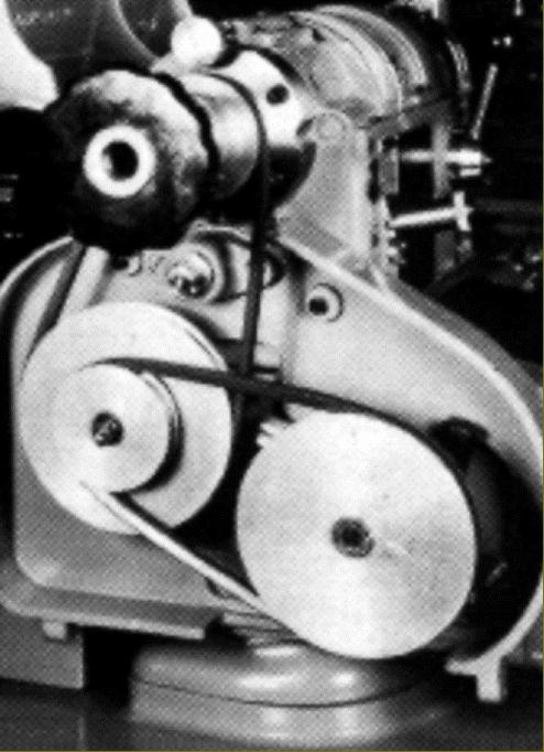
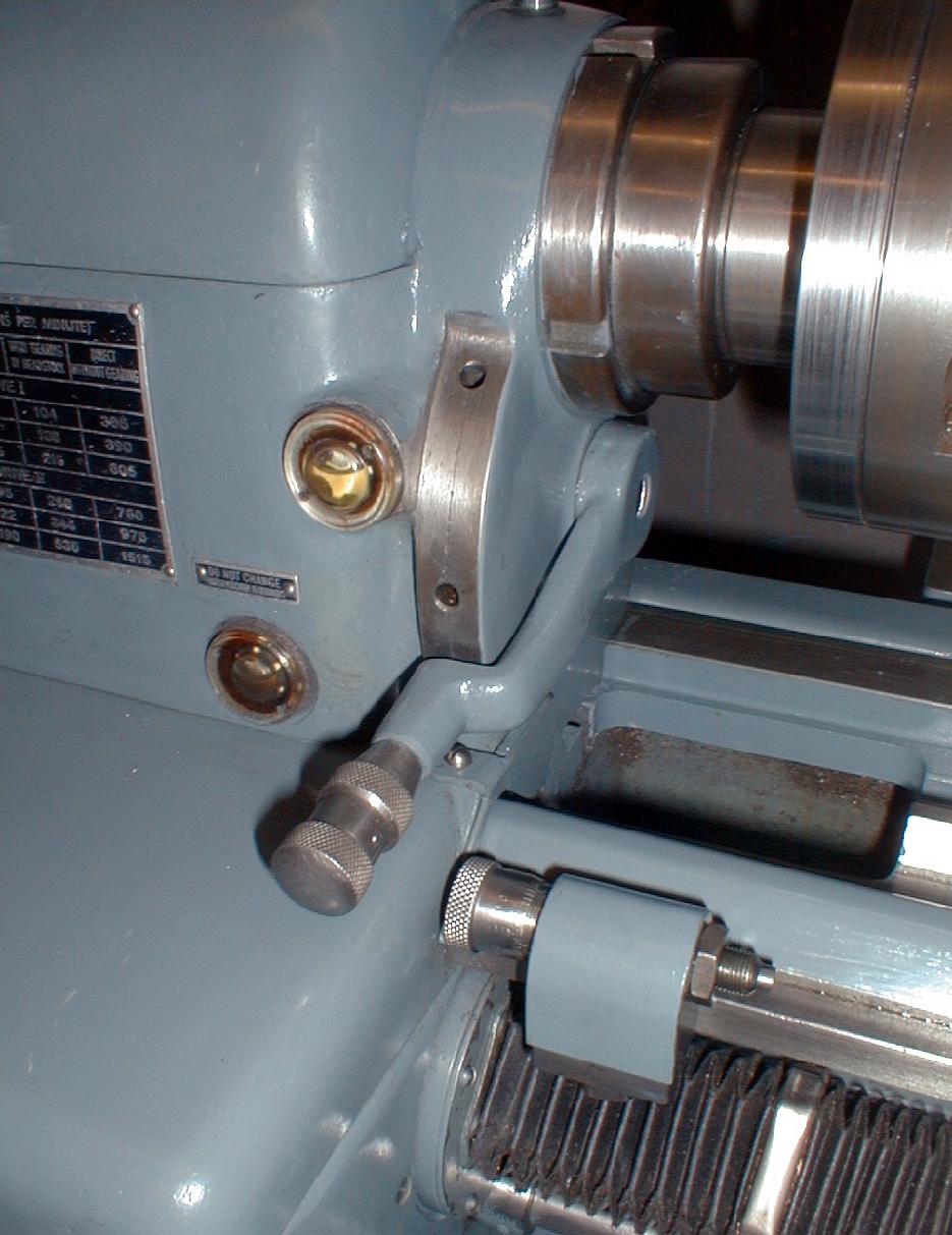
Contained within the very heavily-built, sheet-metal cabinet stand (a number of stands appear to have been offered, not all of which made it into the Company's sales literature) the drive system consisted of a 3-speed, three-phase motor driving a two-speed gearbox. Combined with the single-lever selected, oil-immersed backgear this gave twelve speeds which could be configured, for the MLZ 4S, as either 13.5 to 1515 rpm or 23 to 2220 rpm - and for the LZ 4S as 13.5 to 3030 rpm. Later configurations, with two-step pulleys on the motor and gearbox-input shaft produced 24-speed drives, again with a choice of three speed ranges:
Range A 13 to 1567 rpm - both lathes
Range B 23 to 2170 rpm - both lathes
Range C 13 to 3135 rpm - LZ 4S
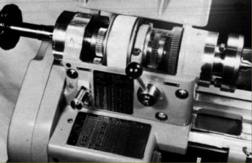
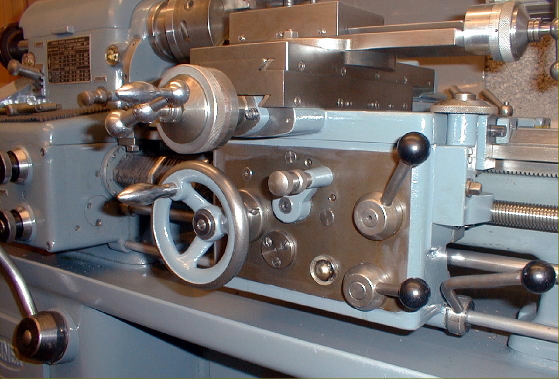
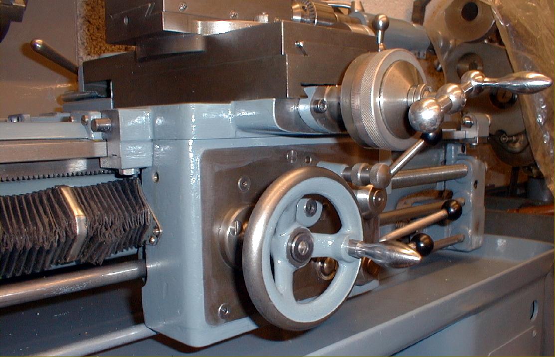
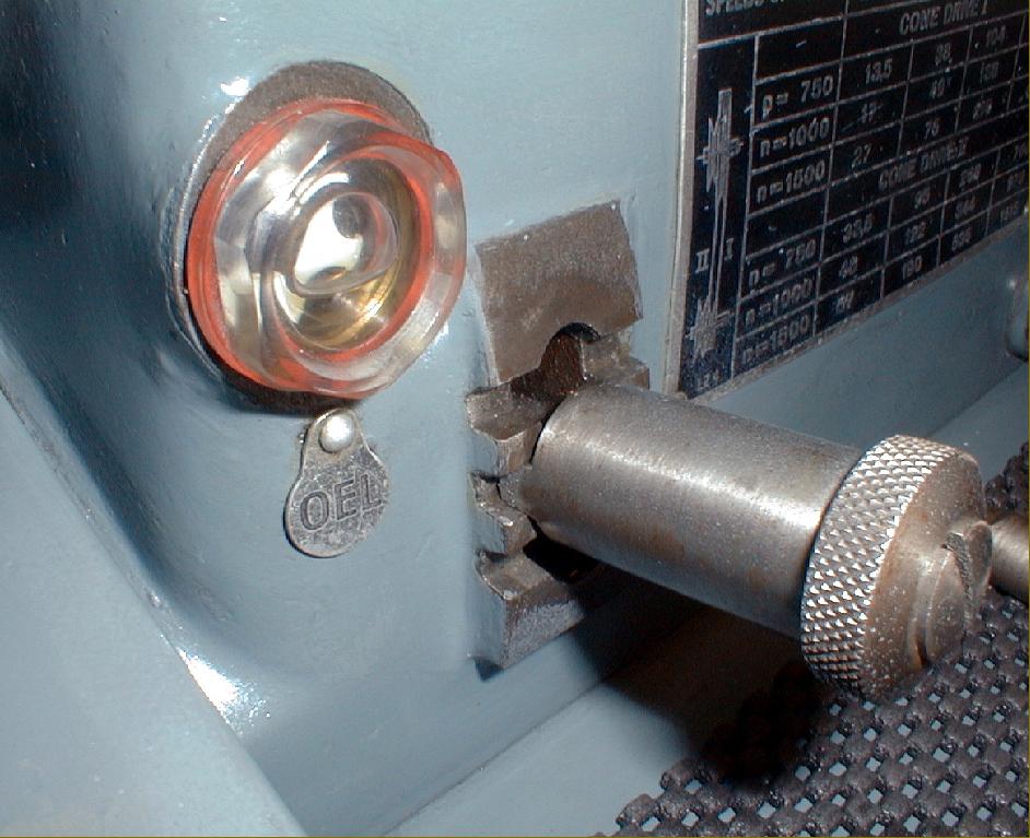
Limit stops, fitted with trips, were fitted to both the sliding and surfacing feeds, with those for sliding being provided with micrometer-adjustment collars. The lowest of the three shafts along the front of the bed operated an electrical stop-start-reverse with the operating lever pivoting from the apron's right-hand face. In addition to the backgear assembly, each headstock bearing, the apron, screwcutting gearbox and speed-change gearbox all ran in their own oil bath.
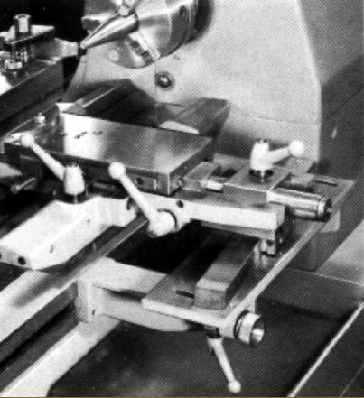
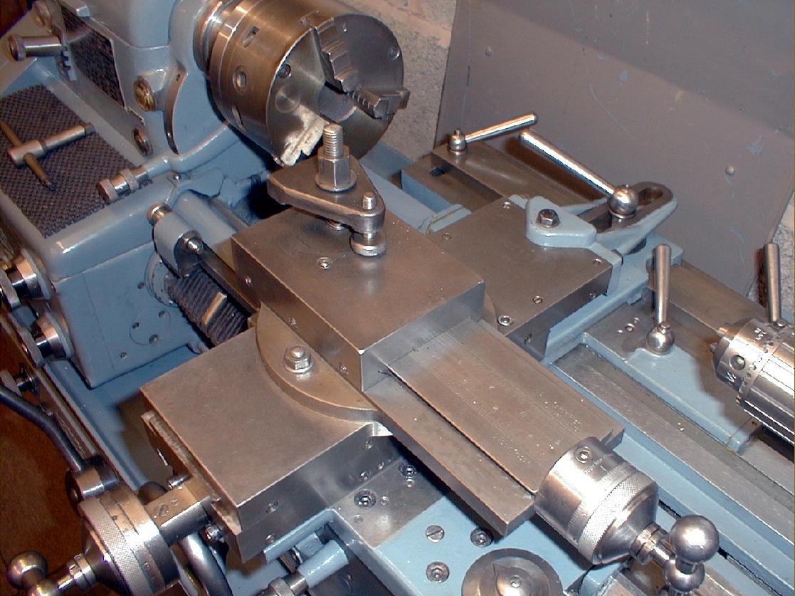
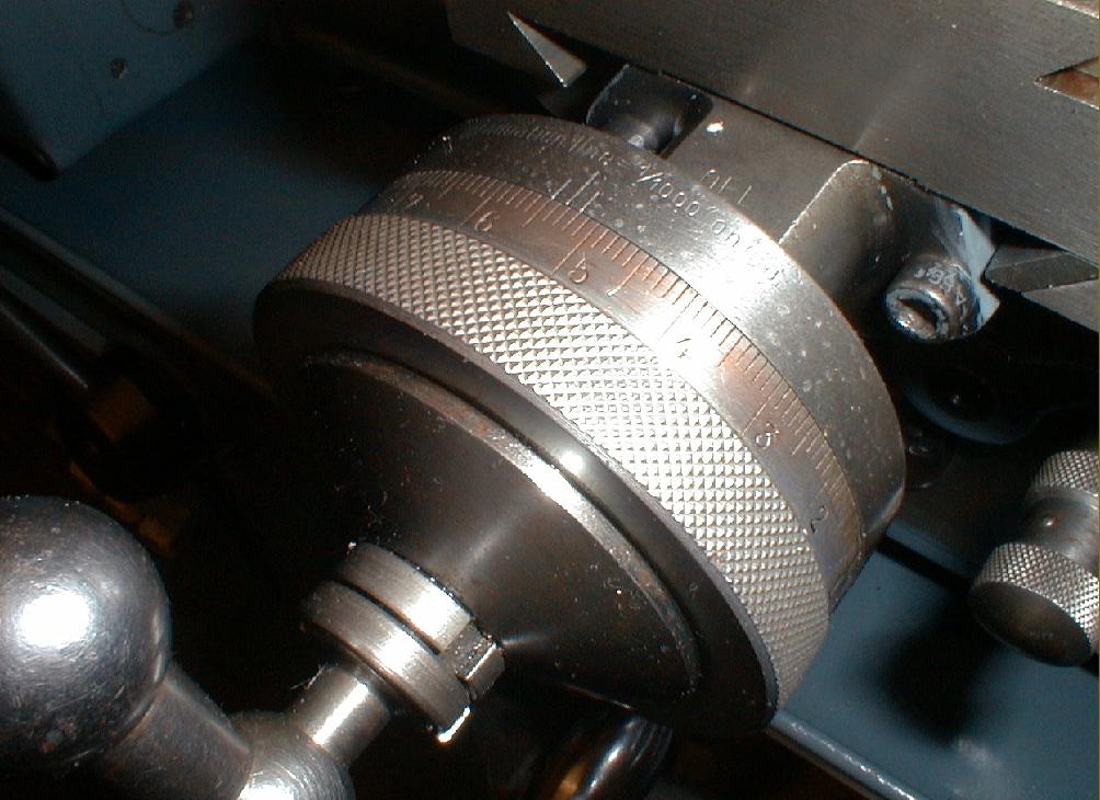
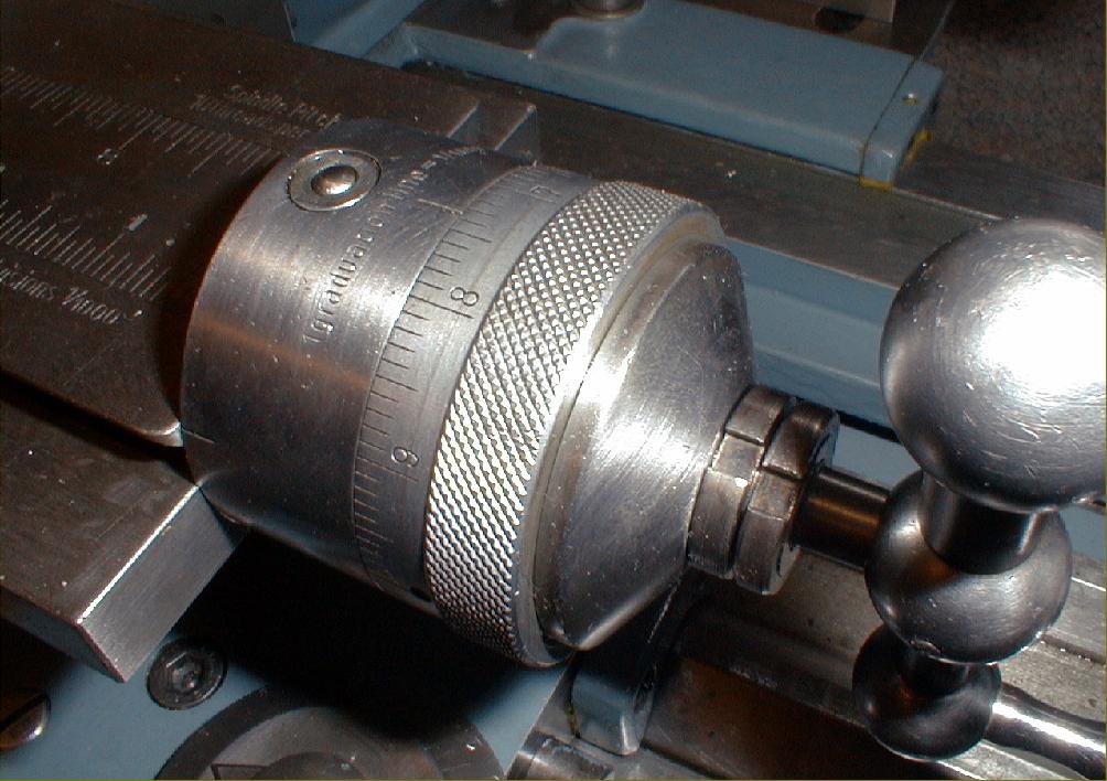
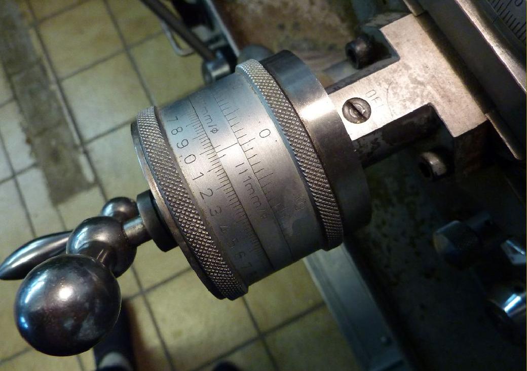
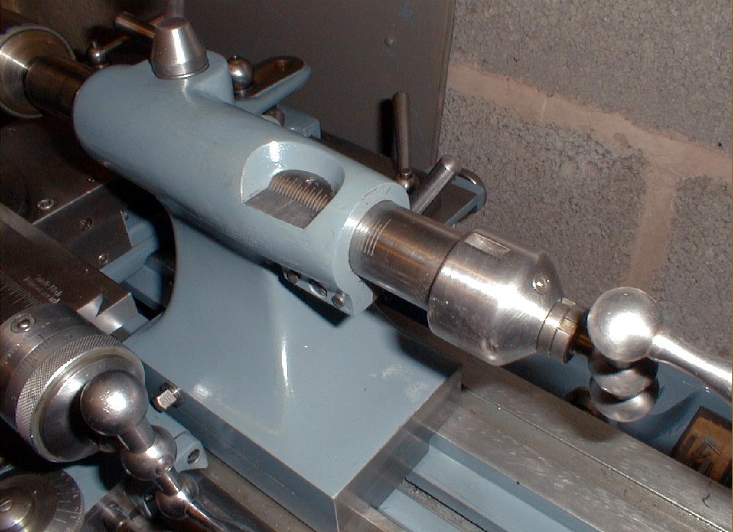
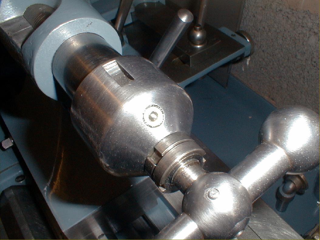
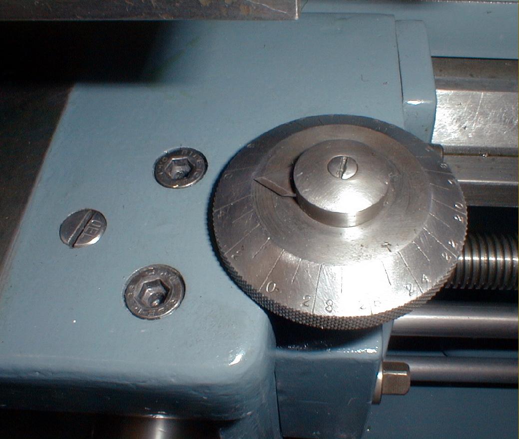
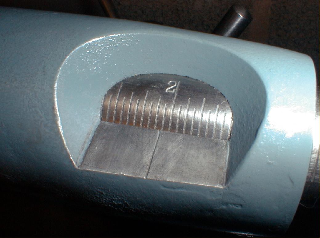
On models with taper turning a clever system of one cross-slide mounted upon another was used, the idea being to bring the unit into operation with the minimum waste of time. For the Leinen designers to have employed this unusual method the consequent loss of rigidity between cutting tool and bed must have been negligible. No effort or expensive was spared to make these lathes as accurate and user-friendly as possible with many thoughtful and detailed touches: the micrometer dials were paragons of efficient design with fine, crisp knurling, a silky feel yet giving a firm setting once positioned; the top of the cross slide ways were engraved with inch and metric ruler scales; a stout bar was provided to lock the headstock spindle (to ease the changing of spindle-nose fittings); simple but effective control knobs and levers abounded, all long enough to enable oil fingers to get a safe grip and convince the operator that he had a firm lock (without resorting to a hammer as was necessary of some makes) while the thread-dial indicator had a large diameter and hence easily-read top scale.
From it's introduction the lathe was continuously developed and improved with several changes to the drive system and stand. Although the apron and screwcutting gearbox were different, the headstock, bed and compound slide rest of early L4Zs were remarkably similar to those used on the lathes made during the 1950s and 1960s. The first stands, in heavy cast-iron stand, were well appointed, having both a full-length wooden tool tray and storage for collets and changewheels beneath. Over the years the stand gradually changed, becoming more enclosed until finally replaced by a much more modern-looking full cabinet, complete in some cases with storage capacity, at some point in the early 1950s.
Instead of a cumbersome, rear-drive countershaft, the flat-belt drive to the headstock on the early versions came from underneath; the difficulties of engineering the installation within the confines of a traditional stand were overcome by shaping the headstock-end leg to hold a beautifully made (and complex) multi-plate clutch/drive unit.
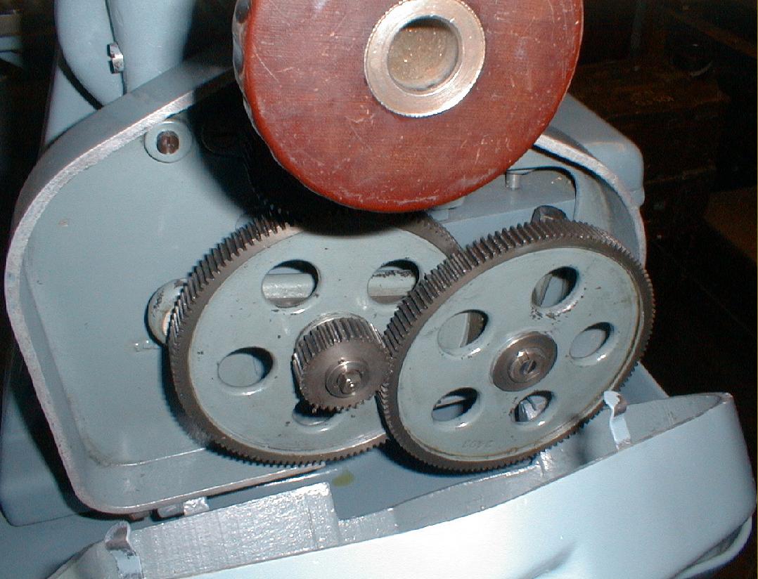
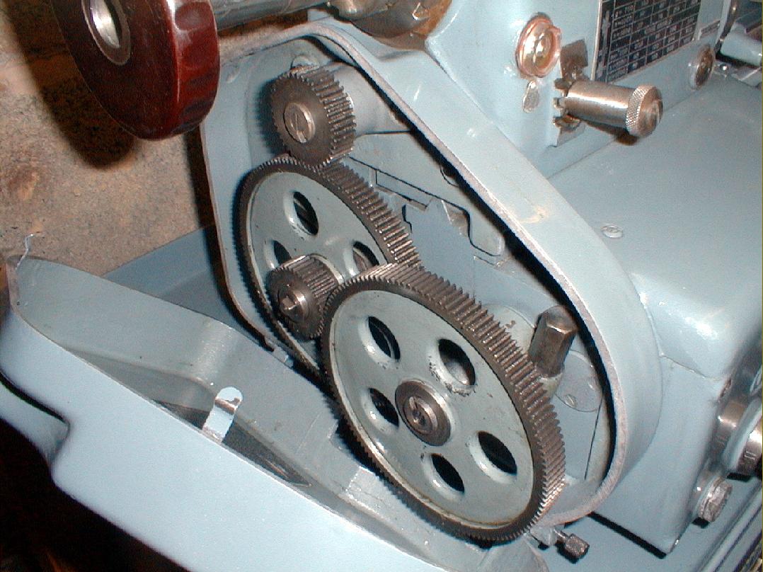
At first just a changewheel model was made, though even this, from the first produced, was fitted with a 6-speed box that could direct the drive to the very large diameter leadscrew or power-feed shaft. However, within a few years a full screwcutting gearbox version was introduced and became the standard machine Early types with a screwcutting gearbox have been found labelled as the Model D23LZN - and were able to generate a wide range of pitches without needing to alter the setting of the changewheels. Inch threads from 9 to 120 t.p.i., metric from 0.25 to 3.75 and MOD from 0.25 to 3.75 could all be obtained and, to extend the range even further, included with the box was a set of ten extra gears: 32, 35, 35, 40, 60, 90, 95, 110, 120 and 127t.
Spares and service for these Leinen lathes might still be available from:
FKW-Kilgenstein (www.fkw-gmbh.de)
More pictures of early screwcutting Leinen lathes here, a very late-model MLZ4-STG - and check the hyperlinks at the top of the page for other Leinen Models
If any reader has catalogue pictures of the Leinen range of machine tools, of any age, or a lathe or other Leinen tool they would like to see featured in the Archive, the writer would be very interested to hear from you..
|
|