|
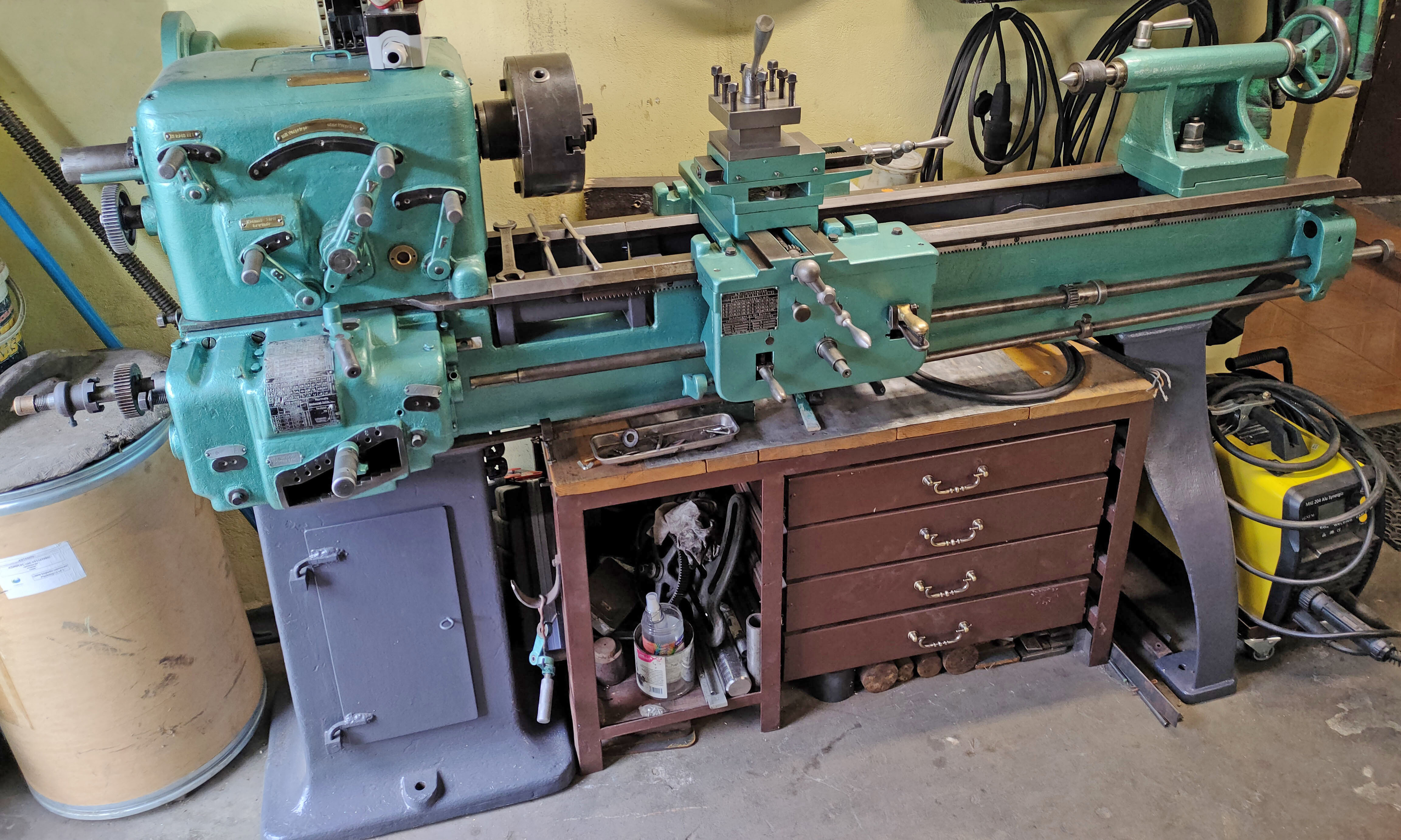
This 6-inch centre height by around 36 inches between centres swivel-head (or swing-head) engine lathe has no apparent maker's mark, but is thought to have been manufactured by Robert Hardie in Albany, NY USA. Hardie, who operated his machine shop from 1856 until his death in 1872, advertised a swing-head lathe in 1860 and, from its general appearance, that would seem to be correct date for the example shown here. Hardie's business, which also made steam engines, boilers, and other equipment, may have operated as late as 1879. The lathe was found in a residential basement where it had been for multiple generations; the location being within a mile or so of where Hardie's Machine Works had once stood.
Fortunately - for what may be the sole surviving example of the type* - the lathe has survived in remarkably original, unmolested condition complete with a full set of changewheels, the faceplate and even with what might be its first "home-made" stand.
Obviously intended as a versatile but light duty lathe - mounting the headstock on four posts would not have encouraged rigidity - its construction must have been an expensive undertaking and the selling price, in consequence, rather high.
While other lathes have had headstocks that swivelled - in the UK the early 3.5-inch flat-bed Drummond lathes were notable examples - few combined this feature with a drive to the carriage. However, one larger lathe that did was the English Barker, an eccentric design that used, like the Hardie, a system of bevel gears and a dog clutch to rotate the leadscrew. In the USA a more widely known builder of swivel-head lathes was George Gage, his Gage Machine Works being situated approximately ten miles north in Waterford, NY. While several surviving Gage swivel-head lathes have survived, they bear little resemblance to what might be a Hardie.
As the headstock on the Hardie could be swivelled - though only by 5 degrees each side of central - drive to the leadscrew started with a bevel gear, mounted on the spindle just inboard of the front bearing. The spindle gear meshed with one on a vertical shaft - the centre line of the shaft being the axis about which the headstock pivoted - with the drive taken downwards to a powershaft, this being split, with each inward-facing end having a bevel gear that engaged with a matching gear at the bottom of the vertical shaft. Either of the powershaft gears could locked into engagement by a dog clutch that sat between them, a horizontal lever being provided to engage the clutch with either the left or right gear (they, of course, turned in opposite directions) - and so reverse the direction of rotation of the shaft. Final drive to the leadscrew was by a gear fitted to the headstock end of the shaft that meshed with a train of changewheels connected to the leadscrew. Only the intermediate changewheel was adjustable, this being carried on a slotted arm fixed to a stud itself adjustable in a radial slot cut into the headstock-end face of the bed.
When the headstock was swung there must, presumably, have been a means of accommodating this on the flat-belt drive system - but perhaps not, the slight angles achieved perhaps being insufficiently steep to cause the belt any real problems (the drive on the Barker was interesting, and worth examining).
Carried on graceful supports - in bronze - bolted to the flat face that surrounded the headstock, the backgear arrangement - being set directly above the spindle - was also unusual though not unique - the Portass "Big Dreadnaught" of the 1950s using the same system.
Fitted with very long, symmetrical wings, the saddle carried a single cross slide with a simple, T-slotted toolpost. Moved by a screw fitted with a balanced handle, the slide was mounted on the centre line of the saddle - the bed ways running on past the front face of the headstock, so allowing the carriage to overlap it and the cutting tool reach up to the spindle nose.
As cutting loads with the tools available during the mid 19th century were low, designers of small lathes paid little attention to the rigidity of the major components hence, although the straight, gap-less bed was noticeably wide, it was shallow in depth and had little in the way of cross bracing, the walls being stiffened by just a few cross ribs of half the wall height. Attached to lobes cast into the underside of the front wall was a machined rack hand feed of the carriage.
Typical in outline shape for its day, the tailstock sat on a separate bridge piece that ran on its own V and flat bed ways. The bridge was machined with two transverse V-ways that allowed the top section to be offset - with an engraved bronze strip - its curved outline reflecting the contours used elsewhere on the lathe - provided to gauge the setting. The spindle lock was of some complexity, being arranged as a surrounding bronze ring drawn upwards by top-mounted handle.
*However, it is reported that another lathe, similar to the Hardie, but larger, has been found - this too being located not far from Albany. Although pictures for publication are awaited, it does appear to have been made by the same builder with its swivel head also mounted on columns (these being elegantly fluted), an identical arrangement of backgear and the same design of hinged leadscrew half nut with a cam lever to close it and a hair spring to assist opening.
Some pictures are high-resolution and may take time to load
|
|