|
Continued:
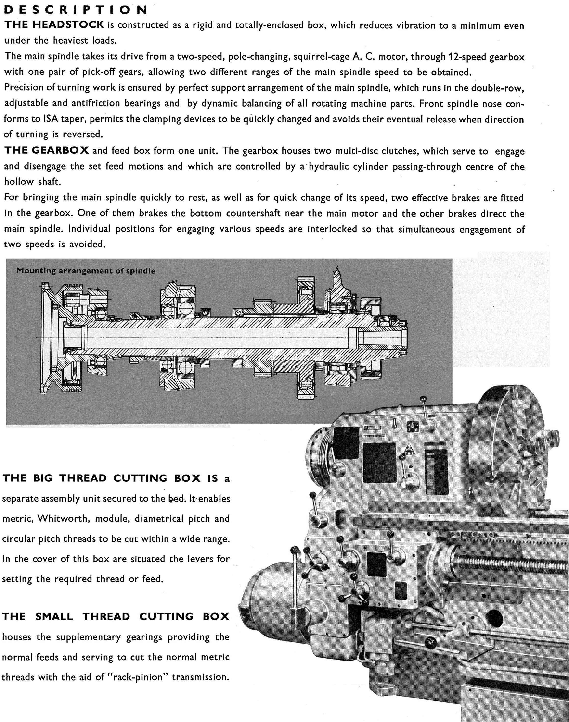
Hardened and ground and running in adjustable bronze bearings (with drip feed oilers on early versions and a cast-in oil reservoir on later), the spindle had a No. 11 Brown & Sharpe taper (a No. 12 was used on the B) with the arbor - a 1.5" unit was supplied as part of the regular equipment - retained by the usual draw bolt. With the draw bolt removed, to release the arbor from its taper, the makers provided a threaded sleeve the turning of which broke the connection. The outer end of the arbor was supported in a bushing some 6.125" in diameter (secured to the frame by an expanding bolt) that, when removed, allowed mounted cutters up to 6.5 inches in diameter to pass through. Driven originally by a 2-speed countershaft running at 225 and 275 r.p.m., with a combination of a 3.5-inch wide flat belt and a gear mounted directly on the end of the arbor, the makers claimed: this is more driving power than is found in any other milling machine e of its size and weight. The introduction of such a spindle-mounted gear would have, like the backgearing on a lathe, have added to the machine's ability to transmit torque, though of course at a reduced speed. Indeed, as a consequence, the maximum spindle speed was very low, and the feed rates gradual. Fitted as standard was a very effective coolant system consisting of a very low RPM gear pump, and a full-length distribution pipe above the arbor. To ensure that the coolant went where required, the pipe was cross drilled with numerous outlet holes with each tapped and plugged with a slotted machine screw, the operator being able to open them as required.
Astoundingly, one Briggs miller is still in productive use, and the owner writes: Regarding operation of the machine, it is best classed alongside endeavours such as watching paint dry and grass grow. Glacial is a good descriptor. One can easily count the revolutions of the spindle at top speed as it is currently configured with the Lima drive (we only run the Lima in fourth gear, as the slower speeds would require time-lapse photographic equipment to record spindle movement). The other notable feature when running is the deathly silence. Lima drives appear to be very quiet systems, and when coupled to such a low-geared machine, there is an almost total absence of drive and feed train noise. A rather soft whir from the motor is about all that is noted when not under cut. There isn't even any belt flapping. When working, the sound is louder, but still quite soft, a low crunching sound dependant upon the cutters used, feed-rate, nature and character of the material, etc. We used the machine almost exclusively for production of 8-foot long guide bars (1" x 3/4") that had to have a 4" radius cut in the 1" face along the entire length of stock, and to "square-up" T-bar with a ganged cutter. Both operations, especially the one with the 8' bar, were time intensive. However, with the trip dogs properly set, all one had to do was configure the jigs correctly, start the machine, pull up the feed lever (the handle just below the large table traversing wheel), and walk away. Since the machine is so quiet, one had to occasionally walk over to check if the table had reached the end of it's travel. The construction of the dogs and feed lever system is extremely positive, and never has the machine failed to disengage when set.
The advertisements tout the rigidity of the Briggs miller as one of its strongest points. I have to agree. While I have never pushed the machine to the limits to see what it would do, in all the many years my family and I have operated it, I do not ever, and I mean EVER, recall the mill chattering. I have on rare occasions chocked it up and slipped the belt, but never a chatter. The finish the machine leaves is very smooth, similar to that produced by a shaper or planer, and is solely dependant on the sharpness of the cutter.
While easy to operate, setting up the Gooley-Edlund can be the proverbial PITA. Indicating a jig is simple enough; just clamp the dial on the arbor, and crank the table back and forth. The fun begins when you attempt to get the cutters "central" with the work. Strict attention must be made in the selection of arbor spacers before you ever install the arbor. As noted, there is only about 5/8" of side travel allowed in the spindle, and this requires that the cutter(s) be quite close to where they ultimately will be positioned for the cut. Several trial cuts are the usual order of the day as you tweak the settings. To adjust the spindle from side to side, you must first loosen the spindle lock ring with a spanner (the right-hand most ring in "A" of the spindle detail drawing), and then adjust the inner ring "A" in conjunction with ring "B". If the position of the machine is as it sits now, with a Kempsmith mill on one side, and an Index mill on the other, this entails walking back and forth around the other mills to make the adjustment (forget having to remove the stupid OSHA mandated belt guard). I digress. Unlike the drawing, the example I own has a clearly graduated bevelled dial on the spindle-side "A" ring to assist in accurately positioning the arbor. Graduated in thousandths, the dial's large diameter coupled with the very fine threads permit accuracy to the "ten-thousandth" relatively easily. The table height adjustment is also similarly accurate. While all known contemporary pictures of the Briggs show no mounted crank or wheel for the "Z" axis, mine is fitted with a very large handwheel. I suspect that the addition of the wheel was a running change in design, along with the cast-in oil reservoir for the spindle in place of the drip oiler in period photos (note the separate spindle oiler screwed into the column versus the cast oiler with sliding cover on my machine), and the cast-in name "Gooley Edlund Cortland, NY" on the base covers. This is the wheel (sans crank) protruding at angle from under the table just below the feed lever. This wheel is also graduated in thousandths, but lacks numerals or other markings, and all graduations are of the same length across the bevelled surface. The size of the wheel (slightly smaller in diameter than the table wheel) permits wide spacing of the graduations, and great accuracy in setting the depth of cut.
My father and I always liked running it, and appreciated it's reliability, outstanding finish, and compact design. Not a "toolmakers" mill, but for what is was designed to do, the production of accurate, duplicate parts, it has surpassed most other machines I have run over the last 30 years.
|
|