 |
 |
 |
 |
 |
 |
 |
 |
 |
 |
 |
 |
 |
 |
 |
 |
 |
 |
 |
 |
 |
 |
 |
 |
 |
 |
 |
 |
 |
 |
 |
 |
 |
 |
 |
 |
 |
 |
 |
 |
 |
 |
 |
 |
 |
 |
 |
 |
 |
 |
 |
 |
 |
 |
 |
 |
 |
 |
 |
 |
 |
 |
 |
 |
 |
 |
 |
 |
 |
 |
 |
 |
 |
 |
 |
 |
 |
 |
|
|
|
|
|
|
|
|
|
|
|
|
|
|
|
|
|
|
|
|
|
|
|
|
|
|
|
|
|
|
|
|
|
|
|
|
|
|
|
|
|
|
|
|
|
|
|
|
|
|
|
|
|
|
|
|
|
|
|
|
|
|
|
|
|
|
|
|
|
|
|
|
|
|
|
|
|
|
|
|
|
|
|
|
|
|
|
|
|
|
|
Manufactured by Golay-Buchel of Lausanne, Switzerland the "Favorite" lathes were but one part of a vast array of horological accessories turned out by the Company. Like Boley in Germany they offered a complete product range from the tiniest screwdriver through staking sets to micrometers, vernier gauges, precision drills, taps, dies, engraving machines and even electro-plating kits. Their 325-page catalogue was a treasure trove of mouth-watering items designed to help the watch and clock repairer undertake every conceivable task.
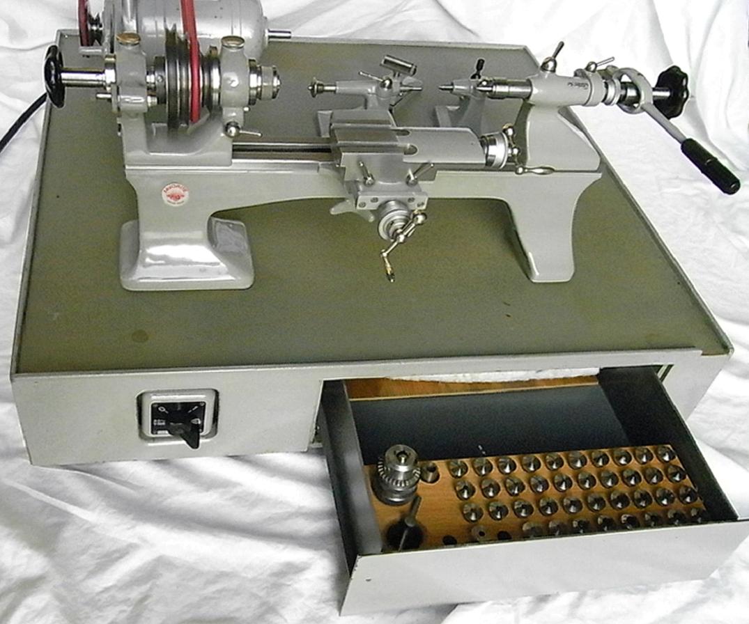
Built in three versions - the Model 1, a 40 mm centre height traditional light Geneva-pattern machine, the Model 2 with a 50 mm centre height and the rather heavier and later Model 3--all were, naturally, of the finest quality, built to Schlesinger standards and designed to for watch, clock, jewellery, dental, tool-making and experimental work. Painted in a "hammer-finish" lacquered green paint the No. 2 and No. 3 lathes shared many of the smaller accessories - although some catalogues listed them under different designations. Although by the mid 1950s the No. 3 had replaced the No. 2 a version of the No. 1, the 1B remained in production for many years, presumably to cater for those watchmakers who preferred a traditional lathe. However, as a larger-capacity machine the No. 3, with its ball and roller-bearing headstock was (like the English IME Model 300) able to tackle a much wider variety of jobs than most machines in this class yet still remain capable of the very finest miniature work.
Although as heavily built as a traditional Webster Whitcombe (WW) watchmakers' lathe - and with the same 50 mm centre height - the No. 2 was a unique design. Instead of using a traditional flat-topped, bevelled-edged bed that on the Favorite was flat, with vertical sides and the headstock, tool rest and tailstock clamped in place by means of a central fastening. When mounted on a single foot (two were an option) the bed was held in a quick-release eccentric slot, allowing it to be easily removed for the close inspection of work or transferred to a bench vice where other accessories--a pivoting attachment for example--could be more easily employed.
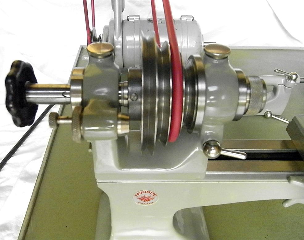
Designed in the days before the cost benefits of a pulley overhung to the left of the headstock became apparent (as on, for example, the just post-WW2 Pultra, the Boley F1 and some Lorch lathes) the 4-step headstock pulley was carried on a hardened, ground and lapped spindle between a pair of adjustable conical bronze bearings. Lubrication was provided by built in capillary-action oilers, a considerable advance on the hit-and-miss oil-can method thought to be adequate by so many competing manufacturers. Instead of a plain, collet-mounting nose the designer provided a substantial thread, backed by a long, supportive register, the intention being to provide as rigid amounting as possible for chucks, faceplates and stepped collet closers. The nose was bored to accept draw-in 8 mm collets (by screw tube or lever-action closer) and the outside face of the largest diameter of the headstock pulley carried two circles of dividing holes - 60 and 48 - with a built-in indexing pin unit. A ring of 12 holes was also drilled into the opposite end of the pulley and intended to be used as a means of locking the spindle when changing nose fittings.
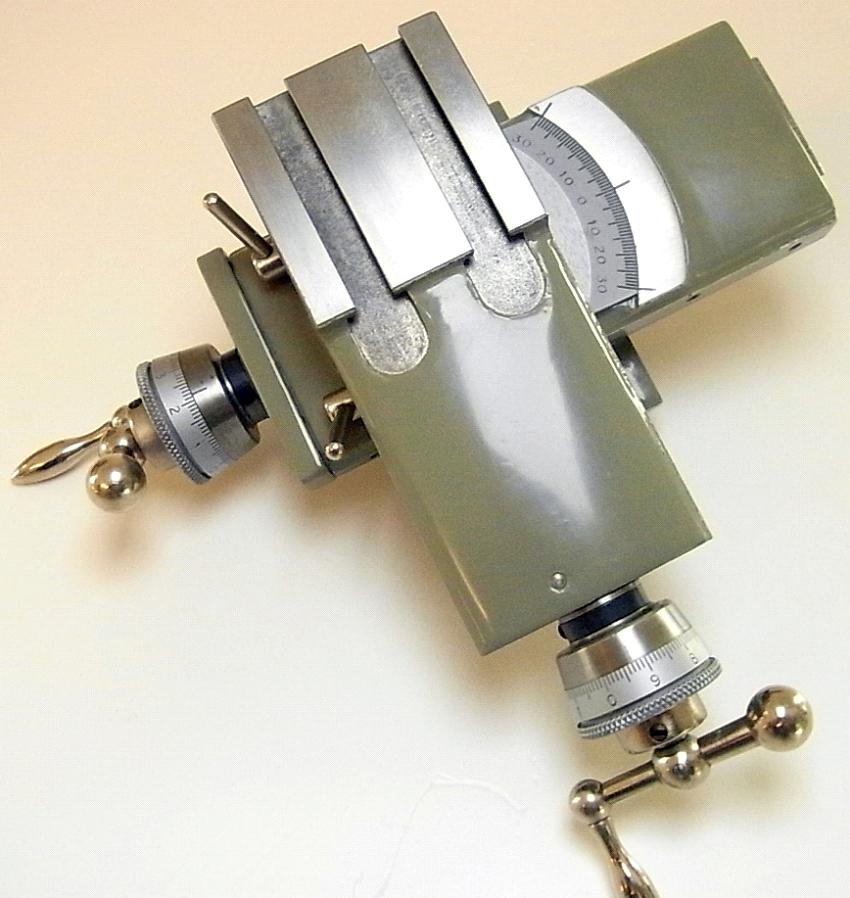
Available with inch or metric feed screws, the compound slide rest assembly registered against the front of the bed and featured fully covered and protected feed screws. The end plate of the cross slide was secured by four screws while two lever-operated clamping bolts were fitted to the top slide to ensure absolute rigidity when mounting high-speed milling and grinding spindles.
Tailstocks with sliding and lever-operated spindles were offered, the latter able to take 8 mm collets and fitted with a micrometer stop for use when drilling. None were fitted with a screw feed, the lever type being judged to have superior feel when undertaking delicate drilling. A special tailstock was also provided, of the horological pattern, for use with pivoting work..
|
|
|
|
|
|
|
 |
|
|
|
|
|
|
Favorite 2 in basic form with cantilever bed (single-foot) flip-up hand tool rest and simple "push" barrel tailstock. In a hard-wood cabinet this outfit was Part 14633
|
|
|
|
|
|
|
 |
|
|
|
|
|
|
Favorite 2 with screw-feed compound slide rest Part F6 and 6-ring chuck
|
|
|
|
|
|
|
 |
|
|
|
|
|
Favorite 2 with double-pedestal bed and all-lever controls - Part F1R collet unit, F6R slide rest and F7 tailstock - for production work
|
|
|
|
|
|
|
 |
|
|
|
|
|
Favorite 2 with gear-cutting equipment: the F20 vertical slide, high-speed grinding and milling attachment and F22 the headstock-mounted division plate
|
|
|
|
|
|
|
|
|
|
|
|
|
 |
|
|
|
|
|
Favorite 2 with horological "mandrel" faceplate and three adjustable jaws
|
|
|
|
|
|
|
 |
|
|
|
|
|
|
Favorite 2 Boxed Set Part 16633. The contents of the hard-wood box varied and could be ordered as required. This particular set has three tailstocks, the compound slide rest, 3 and 6-jaw chucks and a wide selection of collets and smaller accessories.
|
|
|
|
|
|
|
 |
|
|
|
|
|
|
Favorite 2 Boxed Set No. 17633 in a hard-wood cabinet and with an even wider range of accessories and collets including (amongst the more expensive) grinding and milling attachments, the grinding and milling attachments quill, large indexing plate and a mandrel faceplate with 3 jaws.
|
|
|
|
|
|
|
 |
|
|
|
|
|
|
Favorite 2 "Motorised Set" Part 19633. This was available with either a switched 3-phase 1/7 h.p. motor (Part 19633B) or a 1-phase 1/6 h.p. (Ref. 20633A). The assembly could be provided with or without a drawer and with up to 121 accessories mounted within.
|
|
|
|
|
|
|
 |
|
|
|
|
|
|
2-step countershaft with variable-speed 1-phase motor Part 15800
|
|
|
|
|
|
|
 |
|
|
|
|
|
|
2-step countershaft with foot-controlled variable-speed 1-phase motor Part 16800
|
|
|
|
|
|
|
|
 |
|
|
 |
|
|
|
|
|
|
|
2-step countershaft on integrated stand with built-in switchgear and with either 1-phase (Part 13856) 1/6 h.p. motor of 3-phase (Part 10855) 1/7 h.p. motor
|
|
|
|
|
|
|
|
|
|
2-step countershaft with either 1-phase (Part 13852) 1/6 h.p. motor or 3-phase (Part 10853) 1/7 h.p. motor
|
|
|
|
|
|
|
|
|
|
|
|
 |
|
|
 |
|
|
|
|
|
|
|
Standard tailstock F8A with a 7 mm diameter barrel available with male and female points
|
|
|
|
|
|
|
|
 |
|
|
|
|
|
8 mm collet headstock Part F!. This unit was fitted with "automatic" lubrication and 3 rings of division holes: 12, 8 and 60
|
|
|
|
|
|
|
 |
|
|
|
|
|
|
Drilling Tailstock with lever-action control and the ability to take 8 mm collets
|
|
|
|
|
|
|
 |
|
|
|
|
|
|
|
|
|
|
|
|
|
Compound slide rest with covered feed screws Part F6. The friction micrometer dials carried 1/100 mm or 1/000-inch divisions
|
|
|
|
|
|
|
 |
|
|
|
|
|
A rare and expensive accessory--the centring lens assembly Part 13573 with 5X magnification and a recticle with cross lines and concentric circles
|
|
|
|
|
|
|
 |
|
|
|
|
|
Fixed steady Part F40 with convenient wing-nuts to lock the setting
|
|
|
|
|
|
|
 |
|
|
|
|
|
Favorite 2 miniature Quick-set Toolholder Parts F6B and F6C
|
|
|
|
|
|
|
 |
|
|
|
|
|
The Quick-set Toolholder in position
|
|
|
|
|
|
|
 |
|
|
|
|
|
|
Favorite 2 high-speed grinding attachment Part F19. The unit consisted of three parts: a slotted bracket F21, a quill assembly with a 2-step pulley part F21 and a remotely-mounted driving assembly Part F23 (shown below)
|
|
|
|
|
|
|
 |
|
|
|
|
|
|
|
|
|
Favorite 2 individual parts of the grinding Attachment: top right the mounting plate part F19, bottom right the quill part F23 and left the drive unit part F23
|
|
|
|
|
|
|
|
|
|
|
|
|
|
 |
|
|
|
|
|
|
Top left: Part 10645 F2 standard ring-scroll 3-jaw chuck with reversible face jaws. Top right: Part 10647 universal bezel chuck; bottom left: Part 10648 F2 universal ring chuck; bottom right Part 10649 F2 bezel chuck
|
|
|
|
|
|
|
 |
|
|
|
|
|
|
Part F20 vertical milling attachment with arbor holder. The large division plate, part F22, equipped with proper alidades (sighting arms) carried the following rings of holes: 48, 50, 54, 56, 58, 60, 64, 68, 70, 72, 74, 76, 78, 80, 84, 88, 90, 92 100, 200 and 300
|
|
|
|
|
|
|
 |
|
|
|
|
|
|
Left: the compression collet fitting was supplied in two sizes: the smaller was Part F29A with 3 collets and the larger Part F29B with three collets that gave a maximum gripping diameter of 56 mm. Right: the faceplate carried three traditional, finely-adjustable precision clamps as well as a number of tapped holes.
|
|
|
|
|
|
|
 |
|
|
|
|
|
|
|
Catchplate, various types of split-chuck collets, compression collets, arbors, bell chucks, centres, grinding wheel and milling cutter holders and drive dogs.
|
|
|
|
|
|
|
|
|
|
|
 |
|
|
|
|
 |
|
|
|
|
 |
|
|
|
|
|
 |
|
|
|
|
|
|
|
|
|
|
|
|


