 |
|
|
|
|
|
|
|
|
|
|
|
|
|
|
|
|
|
|
|
|
|
|
|
|
|
|
|
|
|
|
|
|
|
|
|
|
|
|
|
|
|
|
|
|
|
|
|
|
|
|
|
|
|
|
|
|
|
|
E-MAIL Tony@lathes.co.uk
Home Machine Tool Archive Machine-tools for Sale & Wanted
Machine Tool Manuals Machine Tool Catalogues Belts
Books Accessories
Drummond B-Type Power Cross Feed
Admiralty Model (Type B.S.) Lathe
Drummond Admiralty Photo Essay
A variety of Drummond literature is available
Drummond Home Page
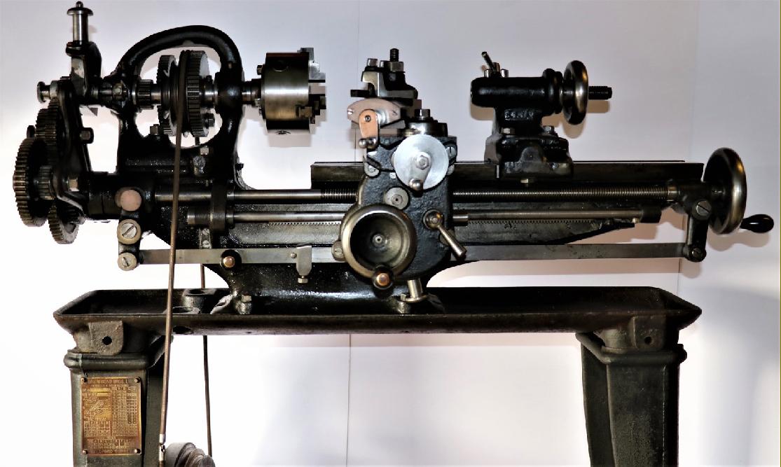
Introduced for Admiralty use at the start of WW1 in 1914, the Mk. 1 "B.S. Type" 3.5" x 15" backgeared and screwcutting lathe included a range of modifications to improve its ease of use on board ships as they corkscrewed around in heavy seas. The most important variations from standard were power cross feed - essential for a good finish in adverse conditions - and a tumble-reverse mechanism. The lathe was based closely on the standard "B-Type", but fitted with the required power-feed apron (with both longitudinal and cross feeds) driven from a shaft fitted below the leadscrew and geared to its left-hand end. A bonus of the power-feed mechanism was a much finer rate of sliding feed than could be obtained by the screwcutting changewheels.
In order to make the assembly work correctly the simple full nut that connected leadscrew to apron was replaced by a proper double clasp nut. A saddle traverse by hand-operated rack and pinion was also fitted to the B.S. and a tumble reverse for the leadscrew drive attached to the slotted bracket on the headstock front - a bracket that normally carried a stud to mount the extra changewheel required for left-hand screwcutting. When the tumble-reverse unit became available on the navel B.S. it also entered the accessory lists for the standard machine - however, the full B.S. specification was only available for Drummond B and M-Types, and Myford M-Type, as was destined exclusively for naval use - it was never offered openly on the civilian market nor, so as far as is known, never featured in any publicity literature.
On the very rare Mk. 1 BS, the power-feed selector arm worked across the front of the apron whilst on much more common Mk. 2 it was positioned to hang downwards and indent into slots machined into the underside face. A standard-fit tumble-reverse assemble was included on all but the earliest models - an essential fitment for shipboard use that gave instantly selectable power feeds up and down the bed as well an in and out. The same unit was to eventually became available as an accessory on the Myford-manufactured M-Type. A fine original example of an Admiralty B-Type is here
|
|
|
|
|
|
|
|
|
|
|
|
|
|
|
|
|
|
|
|
|
|
|
|
|
|
|
|
|
|
|
|
|
|
|
|
|
|
|
|
|
|
|
|
|
|
|
|
|
|
|
|
 |
|
|
|
|
|
|
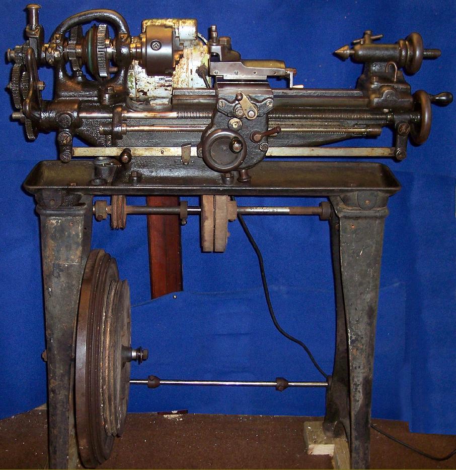
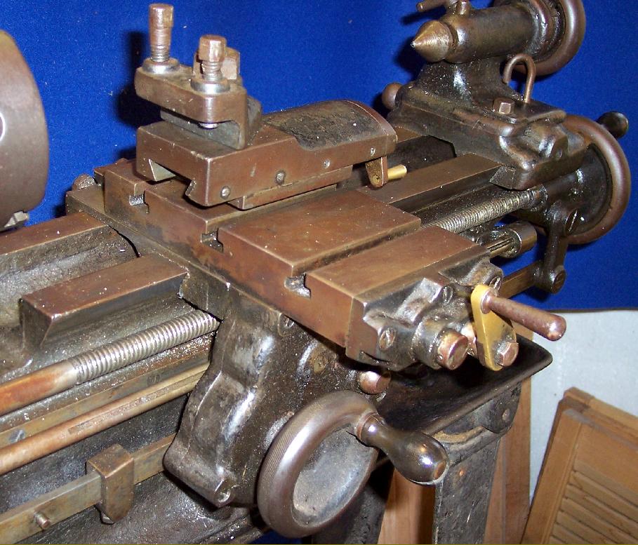
A Mk. 2 Admiralty Drummond B Type. Mounted on the maker's treadle stand and surviving in its original paint, this lathe was bought from an army disposal dale in 1919
|
|
|
|
|
|
|
 |
|
|
|
|
 |
|
|
|
|
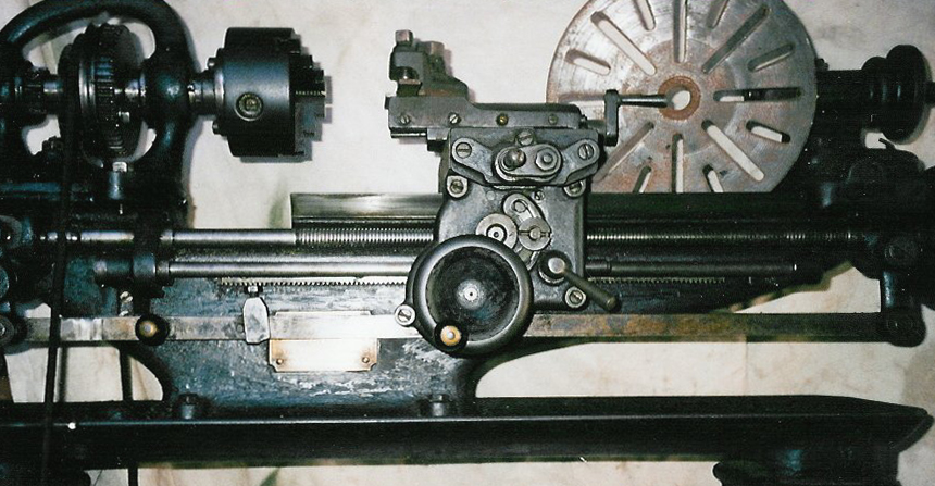
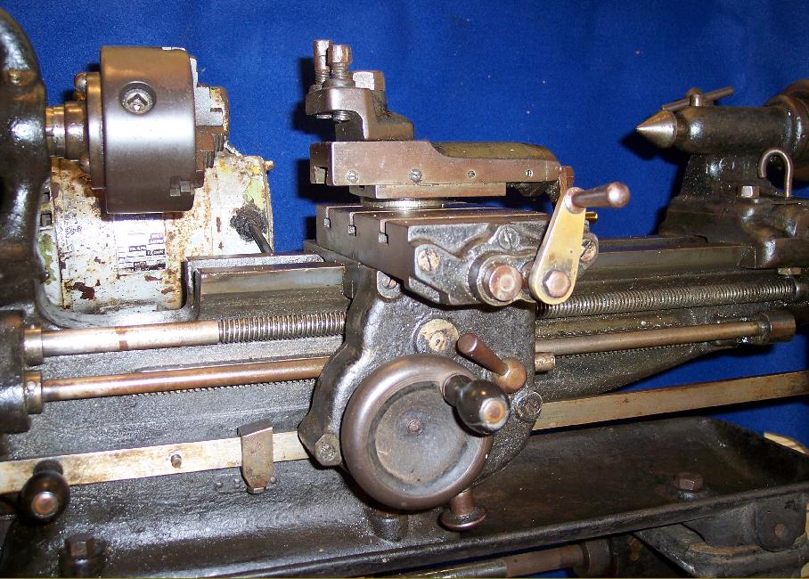
A very rare Mk. 1 BS Type with the power-feed quadrant selector arm working across the face of the Apron.
|
|
|
|
|
|
|
 |
|
|
|
|
|
|
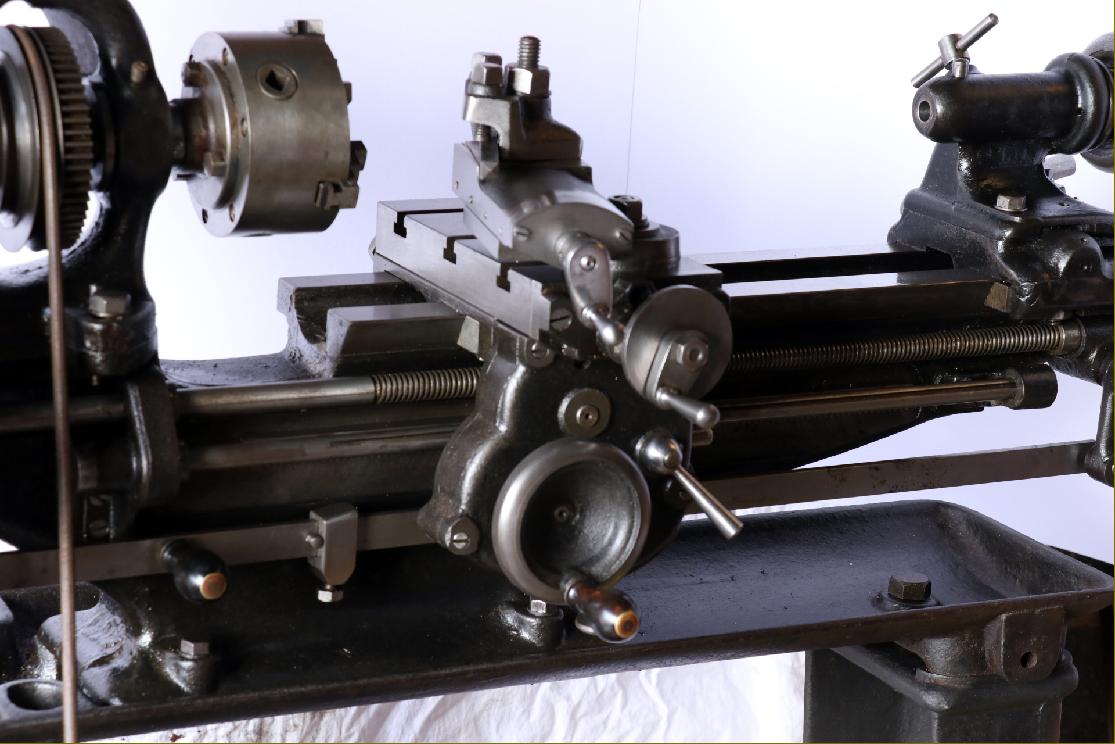
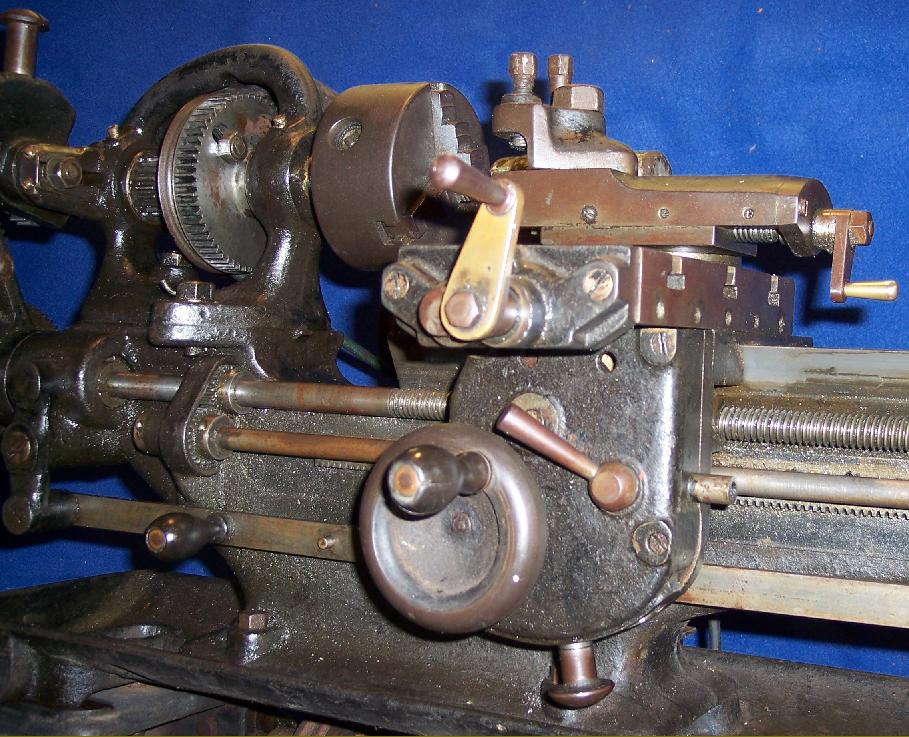
Mk. 2 BS Type
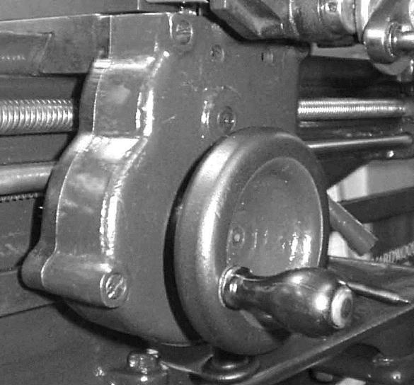
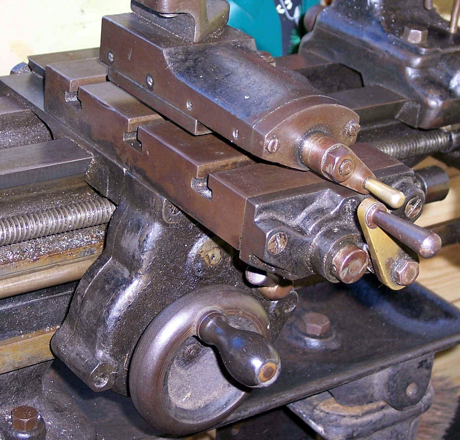
The bottom edge of the distinctly different apron of the B.S. Type carried a spring-loaded quadrant selector with indent positions for hand or power cross feed. The ordinary B had a solid nut on the leadscrew but the fitting of power sliding and surfacing meant that a split nut, that could be disengaged, was required; this was operated by a tapered lever positioned at the top right of the apron. The spring-loaded operating knob that engaged the cross feed was of an identical design (and something of a Drummond trademark) to that used for the engagement and disengagement of the leadscrew clasp nuts on later versions of the lathe.
|
|
|
|
|
|
|
 |
|
|
|
|
|
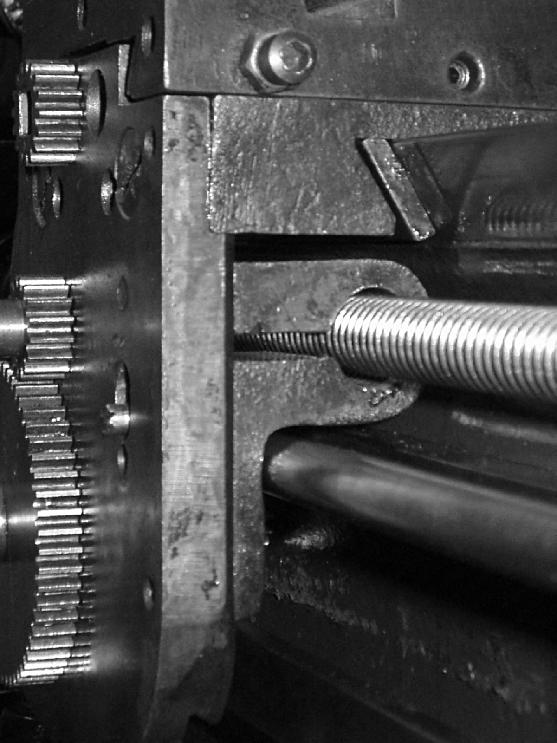
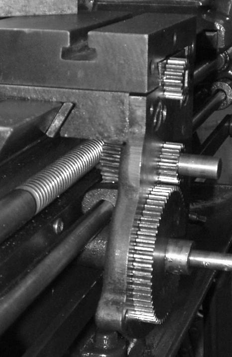
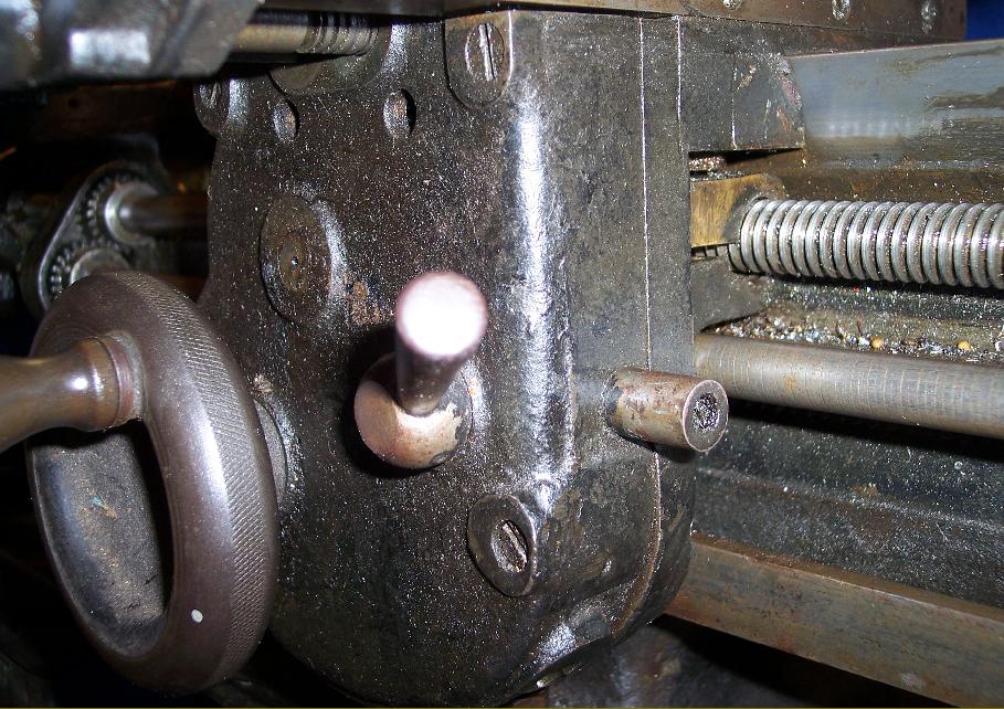
Power was supplied to the apron by a separate shaft, gear-driven from the left-hand end of the leadscrew.
|
|
|
|
|
|
|
 |
|
|
|
|
|
|
|
|
|
|
 |
|
|
|
|
|
|
|
|
Tailstock end of the power-feed shaft
|
|
|
|
|
|
|
|
|
 |
|
 |
|
|
|
|
|
|
|
|
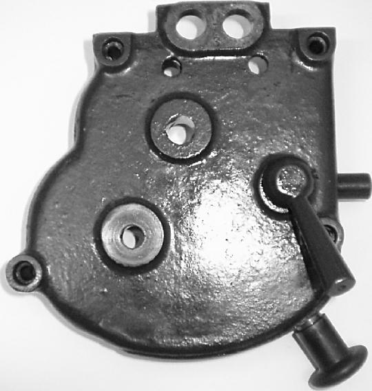
The simple, clutchless, power-feed mechanism was contained within a two-part, cast-iron housing - the inner section of which was secured to the front of the saddle by just two slot-headed set screws.
|
|
|
|
|
|
|
|
|
|
|
|
In order to make the assembly work correctly the simple full nut used on the ordinary model to connected leadscrew to apron was replaced by a proper double clasp nut.
|
|
|
|
|
|
|
 |
|
 |
|
|
|
|
|
|
|
|
|
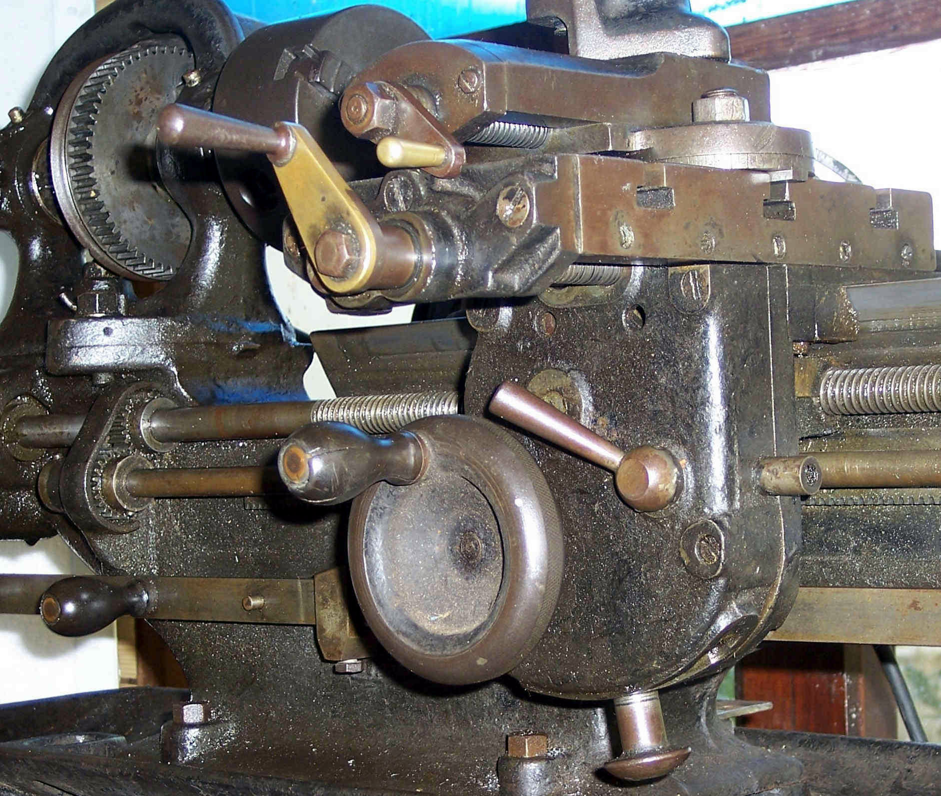
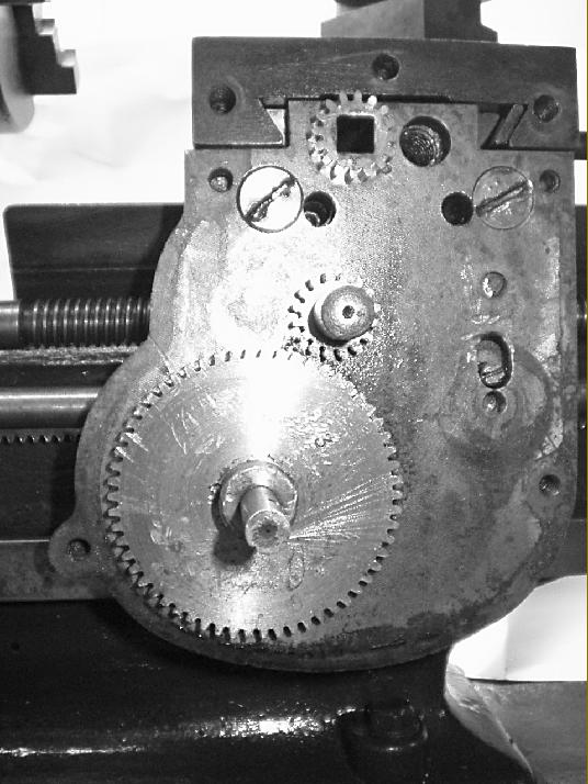
The outer cover held "tumble gears" that selected either power sliding (along the bed) or surfacing (across)
In the picture to the right can be see, at 9 o'clock, the snail-cam mechanism by which means one feed was locked from engagement when the other was engaged
|
|
|
|
|
|
|
 |
|
|
|
 |
|
|
|
|
|
|
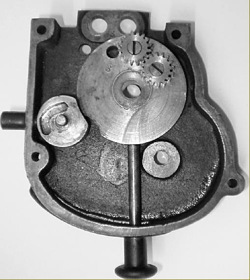
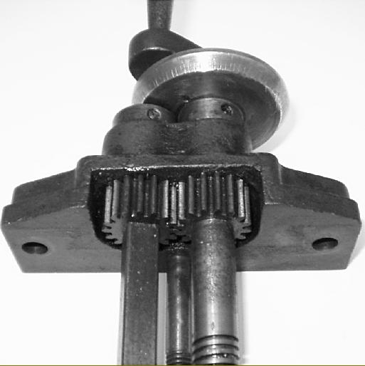
The inner plate was used to mount the feed-reduction and hand traverse gearing
|
|
|
|
|
|
|
 |
|
|
|
|
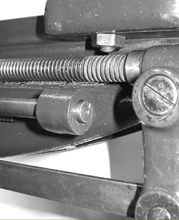
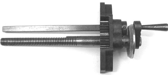
Left and below: the final drive to the cross-feed screw was by a gear connected to the square rod that slid through the upper drive gear.
|
|
|
|
|
|
|
 |
|
|
|
|
 |
|
|
|
|
|
|
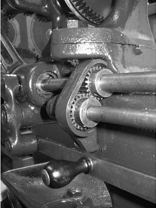
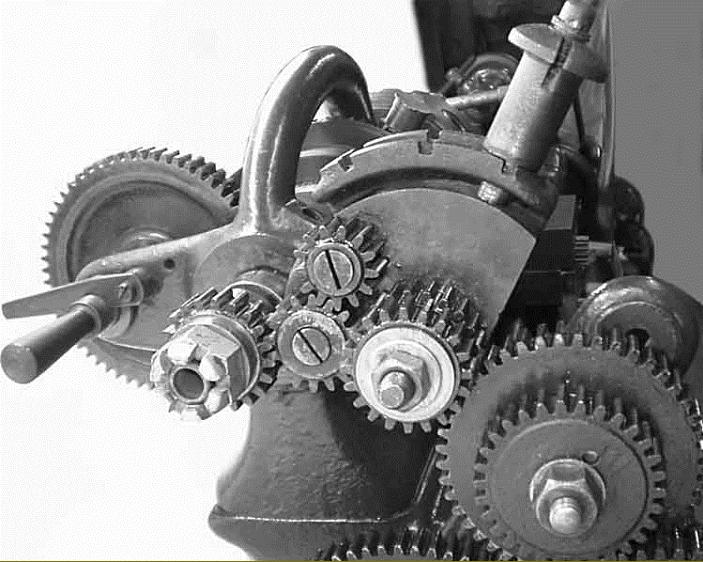
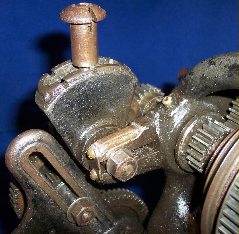
An essential part of the modifications carried out to the lathe to make it suitable for on-board use, was a tumble-reverse mechanism carried in the slotted arm on the headstock normally used to hold the extra changewheel necessary when cutting left-hand threads.
|
|
|
|
|
|
|
 |
|
|
|
|
 |
|
|
|
|
 |
|
|
|
|
|
|
|
|
|
|
 |
|
|
|
|
 |
|
|
|
|
 |
|
|
|
|
 |
|
|
|
|
|
|
Another view of the tumble-reverse mechanism
|
|
|
|
|
|
|
|
|
|
|
|
|
|
 |
|
|
|
|
|
|
|