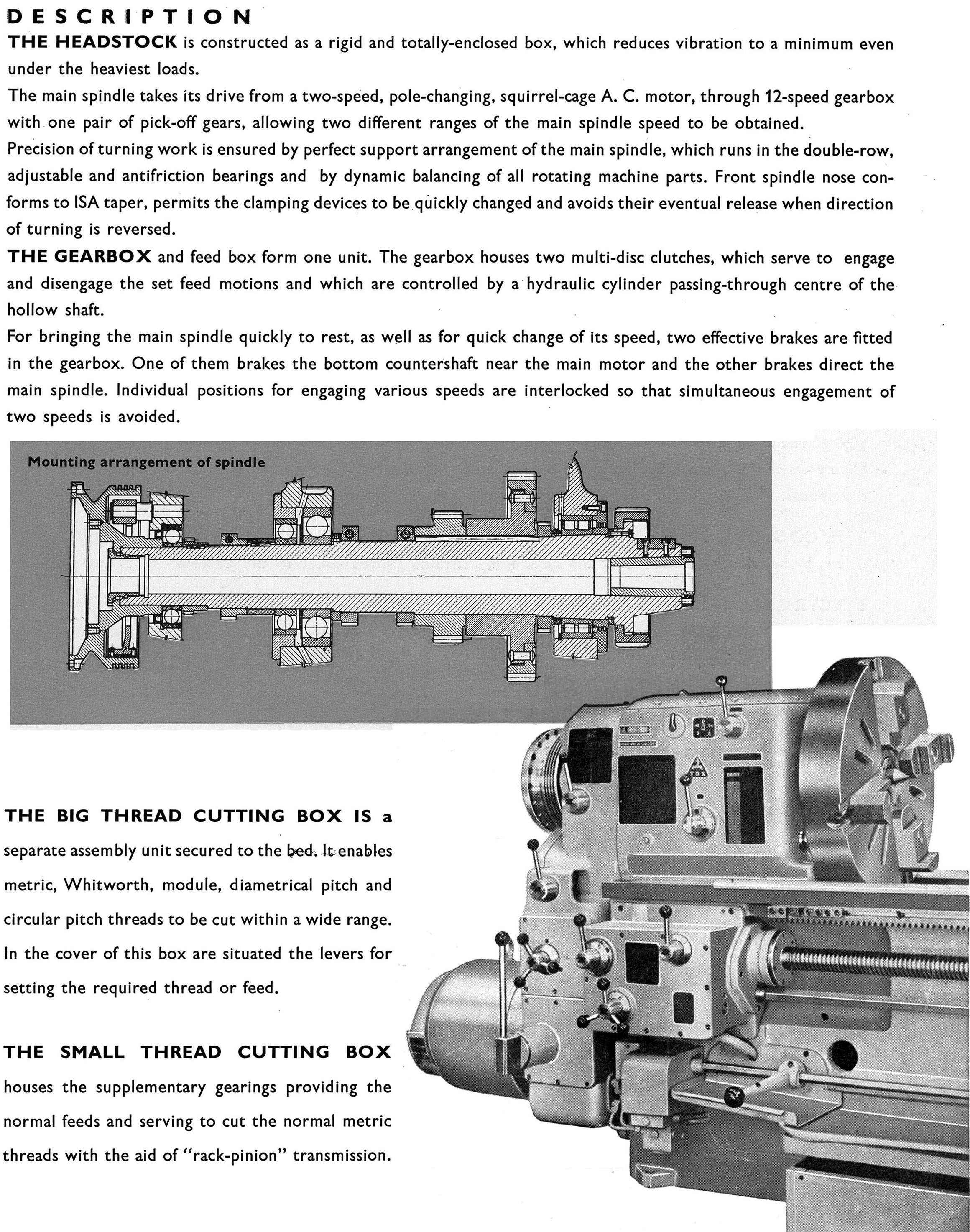
|
A lathe with the bed modified to make an air pump? Surely not? But, yes, here is an antique lathe where that was, indeed, the case. One must assume that, in order to devise this most unusual and ingenious contraption (which might have been built as a prototype but never made for sale) Mr J.A. De Vries must have enjoyed considerable experience in the Jewelry industry. Not only was this claimed to be a practical, ordinary lathe for use by a watch repairer or jewellery maker, but it could also be employed to speed up the process of soldering. How can a steam of cold air - rather than hot - be used to assist soldering? Before the advent of a gas supply the technique - and it is ancient - involves using an oil lamp (or other flame) with the stream of air directing the flame onto the workpiece. Before pumped air was available, air from the mouth was used through a blowpipe.
To this end, the lathe was equipped with an air pump, cunningly built into a hollow bed - that could be swivelled either way around its mounting foot - and with each end of the bed connected to a rubber pipe (Part C). Inside the bed was a piston, fitted with a small block (part D) that guided it back and forth by engaging in a slot cut along the bed's front face (one wonders how this was sealed). The piston had, on each end, an outwardly opening valve, as did each end of the bed. The result was that, as the piston moved air was forced out in the direction of travel but could not return when the piston changed direction. At some distance from the bed, both pipes were drawn together, perforated with small holes and surrounded by a chamber (Part G) where the air pressure was balanced. Each pipe then continued separately and ended attached to a delivery nozzle held on a small support plate by spring clip.
The piston was driven by an arm (part J) attached to it's guiding block and connected, at its other end, to a roller that fitted into an eccentric grove machined into the headstock pulley. The arm and its roller end and the eccentric groove into which it fitted are shown in Fig.1 as part J. As the pulley rotated, the arm was rocked and this motion transferred to the piston.
The top of the bed was formed with a rack (part N) with the headstock able to be repositioned by releasing a locating spring clip. Fig. 4 shows the slide rest, M, the sliding part complete with a toolpost being moved by worm-and-wheel gearing (parts 3 and 4). The whole slide rest could be positioned on the bed by turning the larger of the two wheels shown in Fig 4, this action turning a shaft (part 5) that rotated a pinion against the bed-mounted rack.
I'll leave keener readers to work out from the description how the 3-jaw chuck, with its reversible jaws, was constructed….
|
|