|
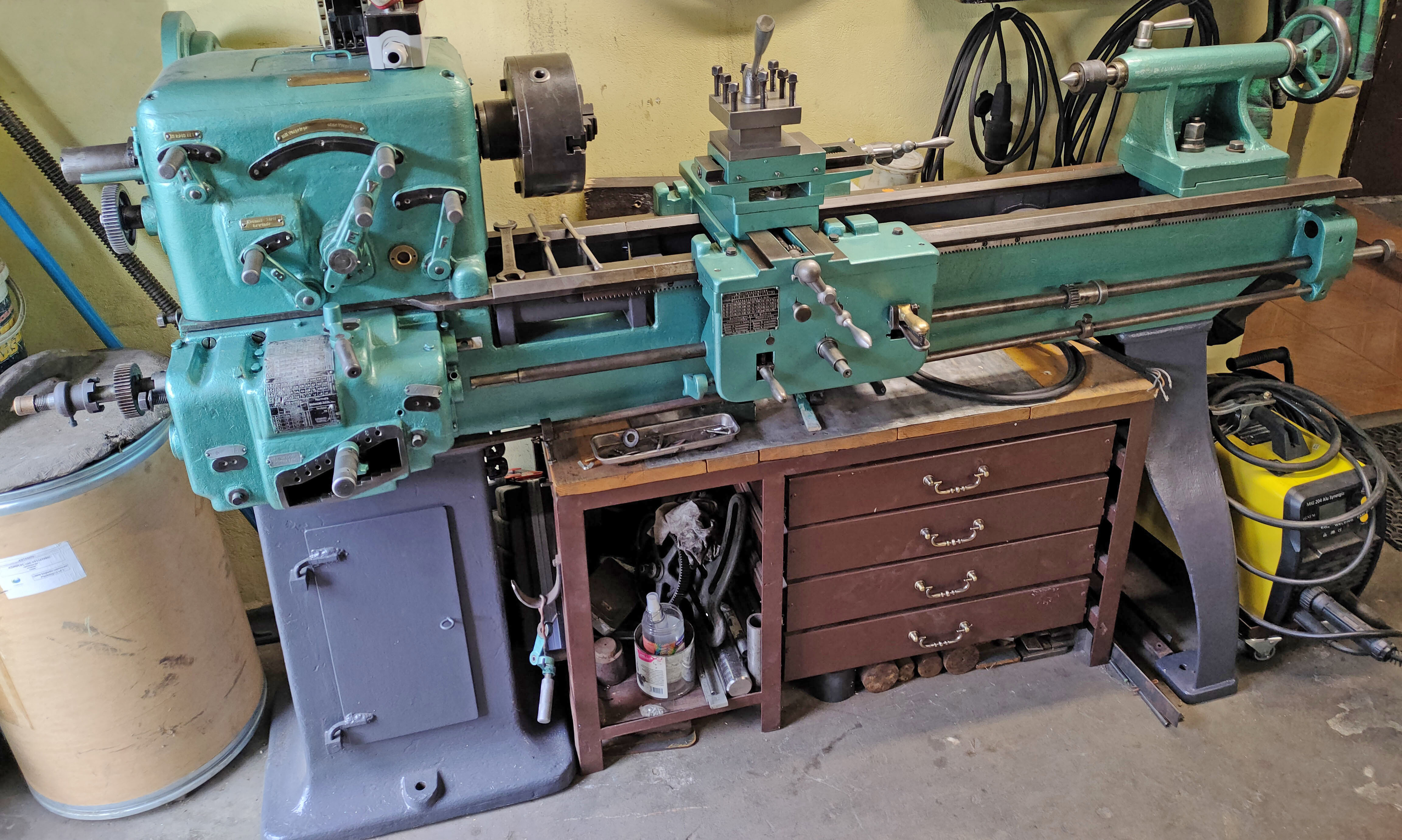
At a glance, the 1888 Conklin watchmakers' lathe has little to distinguish it from any other light-pattern "Geneva" style lathe. The draw-in collet system had been developed my Charles Moseley from a patent taken out by George W. Daniels and a Mr A.Fuller both, together with Moseley, residents in the watchmaking and precision engineering centre of Waltham. For details of this important development see:
http://www.lathes.co.uk/moselely and https://www.lathes.co.uk/daniels-moseley
The headstock bearings, with their opposing outside faces tapered and able to be drawn together to take up wear, was not new either. It might be that the tailstock broke new ground in having a design that allowed for the self-ejection of the centre.
Unfortunately, the patent document is not available in its ordinal form, but only as an OCR version of it, and this process, on poor quality print, with a strange, curvey font, does leads errors. The writer has endeavored as far as possible, to correct these errors - although the last three lines, including bullet point 3, were scrambled. It thus reads:
No. 237,487. Patented Feb. 8, 1881
UNITED STATES PATENT
PHILETUS B. GONKLIN, or NEWARK, NEW JERSEY
LATH
SPECIFICATION forming part of Letters Patent No. 237,487, dated February 8, 1881.
Application filed April 10, 1880. (No model.)
To all whom it may concern:
Be it known that I, PHILETU B. GONKLIN, of Newark, in the county of Essex and State of New Jersey, have invented certain new and useful Improvements in Lathes, of which the following is a full, clear, and exact description, which will enable others skilled in the art to make and use the same, reference being had to the accompanying drawings, forming part of this specification, in which, Figure 1, represents a sectional side elevation showing my invention. Fig. 2 is a side elevation of the same.
Similar letters of reference indicate corresponding parts.
The object of this invention is to construct a neat, cheap, and serviceable lathe especially adapted for jewelers, dentists, and light work, where great accuracy is required.
My invention consists in the various details of construction, which will be hereinafter more fully described, and then pointed out in the claims.
In the case here presented A represents the main frame which supports the whole lathe.
B is a solid round metal rod, which extends through the main frame, and is held adjustably in position by the thumbscrew (C). The said rod (B) has the back head (D) rigidly attached to its extremity by the pin (E) and has a centering line or mark made its full length, so as to enable it to be set at any point with the corresponding work on the main frame, in order that the back head may be set in true line with the front head. That part of the main frame (A) in which the spindle F rests has its bearings made conical to correspond with the inward taper (G) of the forward end of the spindle, and also to correspond with the inward taper (H) of the hub of the balance-wheel, so that by slackening the screw (I) on the hub and tightening the screw (J), which extends through the hollow or raised washer a into the extremity of the spindle, it will allow the wear or lost motion to be taken up, as occasion may require. The chuck (K) is also tapered inwardly, and fits in a corresponding recess in the forward end of the spindle, and is held secure in position by the cap-nut (L) as shown in the drawings.
The tool-rest holder (U) is cored out and fitted on the round iron bar (B) and is clamped in position by the thumb-screw (S). The toolrest W itself is set in a hollow boss, V, and clamped at such angle as required by the thumb-screw T.
It will be observed that by securing the back head fast on the rod (B) and constructing the front head (A) so that the rod slides through it, I can turn the back head and rest both together, and adjust them both by turning a single screw; whereas if the bar B were made in one piece with or fast in the head (A) it would be necessary to loosen two screws to turn the back head and rest to one side of the center.
The bushing (M) which serves to hold the stem of the screw (N) in the back head, is held locked in position by the pin (0).
The traveling socket (P) which is operated by the screw (N) has a portion of its under side cut away, in order to produce a flat surface, so that by inserting a pin, as shown at (Q), the same will be kept from. turning in its travel.
It will thus be seen that by simply removing the pin (0), which looks the bushing, the hand-wheel with screw and bushing may be removed bodily to the rear, and the center or traveling socket be withdrawn from the front of the back head, thereby greatly simplifying the construction and lessening the cost of manufacture.
Having thus described my invention, what I claim as new, and desire to secure by Letters Patent, is
l. The combination, with the front head (A) of the bar (B) constructed to slide and turn in an orifice in said head (A) with the back head (D) securely fastened on bar (B) and turning (0) therewith, whereby both back head and rest may be turned simultaneously, and both adjusted together by the screw (0) substantially as described.
2. In a lathe, the combination of the balance-wheel and tapering hub (H) with the screw (J) hollow washer to, and spindle (F) the same thing constructed, arranged, and operated in being constructed, arranged, and operating the manner and for the use and purpose together in the manner and for the use and scribed purpose described..
|
|