|
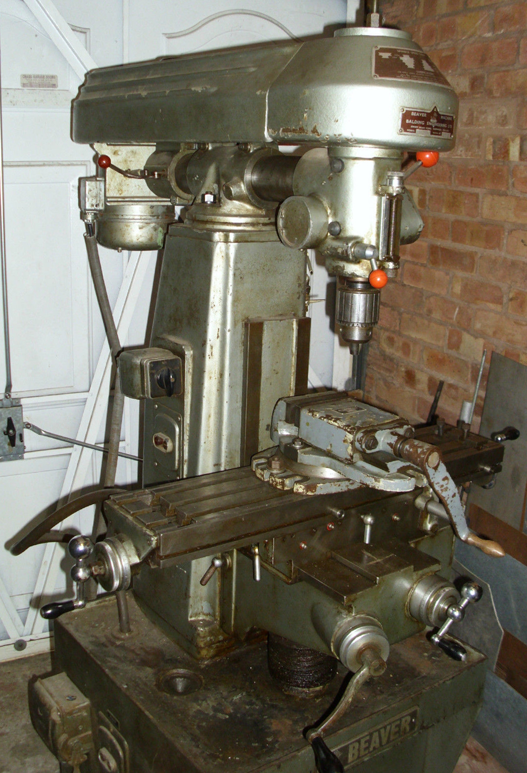
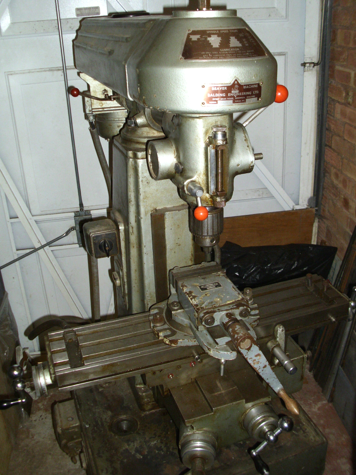
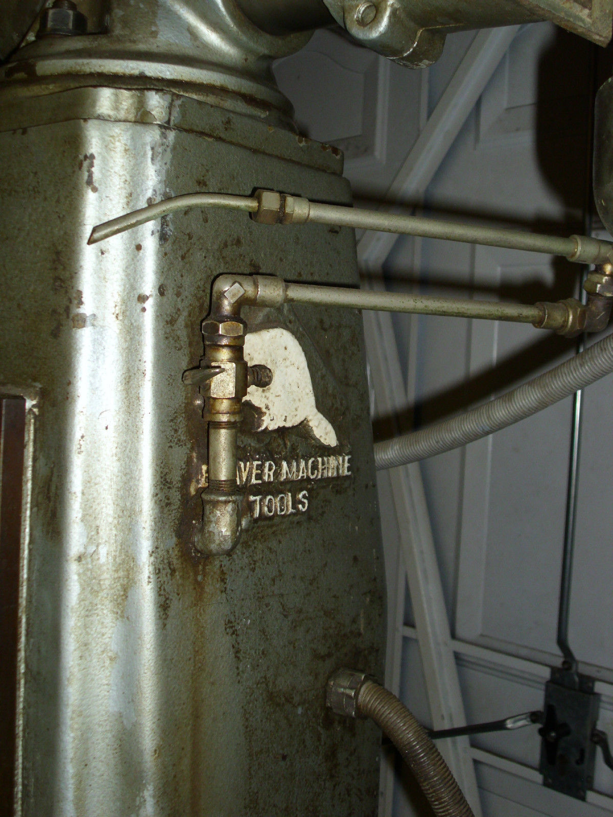
Manufactured by Balding Engineering (originally jobbing engineers) of the Old Tramways Power Station, Duke Street, Norwich (and then Sweet Briar Road in the same city) the Beaver Model "A" milling machine was an interesting "miniature" turret-head type. Confusingly, a batch of these machines was badged as "Grimston" (a London machine-tool manufacturer and merchant) and sometimes lacked the cast Beaver badge screwed to the right-hand face of the column. The paint on the Grimston was often (though not always) rather unusual: a "splatter" mix of dark grey, green and red not dissimilar to the finish also used on some American ROTEX millers of the same era.
In its original form, as introduced during the early 1950s, this little miller proved to be a compact, versatile machine equally at home in the toolroom or on the shop floor - and absolutely ideal when its industrial life was over, for the workshop of the enthusiastic amateur. In the mid-1950s the Model "A" was joined by a scaled-up version, the "VBA", a model that used a much more massive knee and column - but the same vertical head. The table was huge, some 10 inches wide, and available in a fours lengths: 32", 36", 44" or 48". One more small miller was to be manufactured, a very rare horizontal/vertical version of the "A", the "AH" - a machine, that, surprisingly used a one-off vertical head instead of the standard unit on the other types. In 1957 a further, very much larger and heavier miller was introduced, the very successful Mk. 1 and Mk 2 and "VBRP". However, production of the earlier types continued into (it is believed) the mid-1960s. On the back of considerable success in exporting the VBRP range, in the early 1980s the company opened a new factory in Peterborough to manufacture a range of CNC lathes to compliment the CNC millers and CNC machining centres already in production; unfortunately, the severe recession in manufacturing industry of 1992 (when demand for machine tools fell by 50% in 3 months) forced the closure of the company.
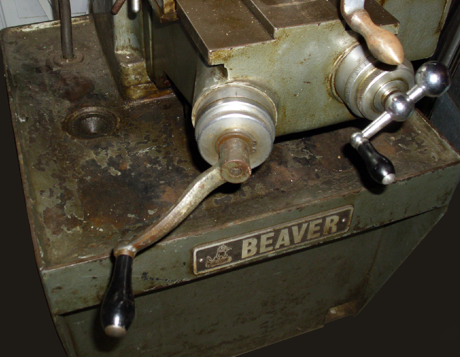
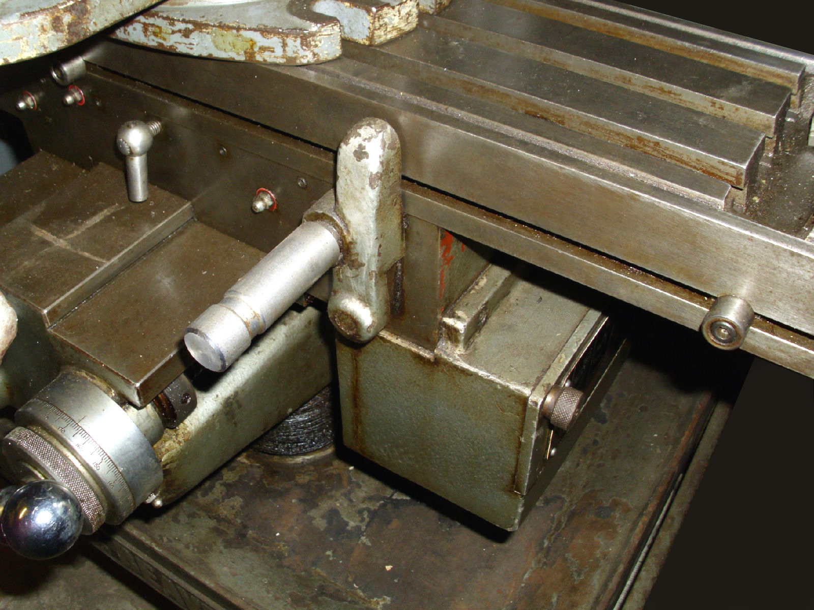
Fitted to a compact but very heavy cast-iron box-section stand with internal ribbing, a built-in chip tray, coolant suds tank and tool storage, the original Beaver "A" had a 3 T-slot 28" x 6" table with a longitudinal travel of 15", a cross feed of 7.5" and a vertical movement of 13.75" measured by decently-sized 3-inch diameter zeroing micrometer dials connected to 0.752 diameter feed-screws made from high-carbon steel with the acme-form thread produced by grinding. The cross and longitudinal feed screws ran through backlash-adjustable double bronze nuts - and with the vertical screw turning on a ball thrust bearing and protected by a telescopic cover. At each end of the table a coolant slot was provided with, usefully, the T slots running through these to maximise the table's clamping area. Both the one-piece main column and top of the knee carried narrow square-section ways with taper-gib adjustment whilst the table ran on V ways with a decent length of support - some 13.75 inches. Balanced ball handles were fitted at both ends of the table - some makers of similar machines economised by providing only one - and power-feed, from a 1/10 h.p. motor working through a 4-speed gearbox was fitted as standard. The customer could choose a feed range of either 0.5" to 4.5" or 1" to 9" per minute, but with changes of rate made by "pick-off" gears where the operator had to remove a panel, pull off the gears (they were retained on their studs by snap-on wire springs) and change them for another pair from the four supplied. However, the table feed worked in both directions, with selection by a lever that gave an instant reverse combined with an automatic disengage tripped by stops fitted into a T-slot that ran down the table's front face.
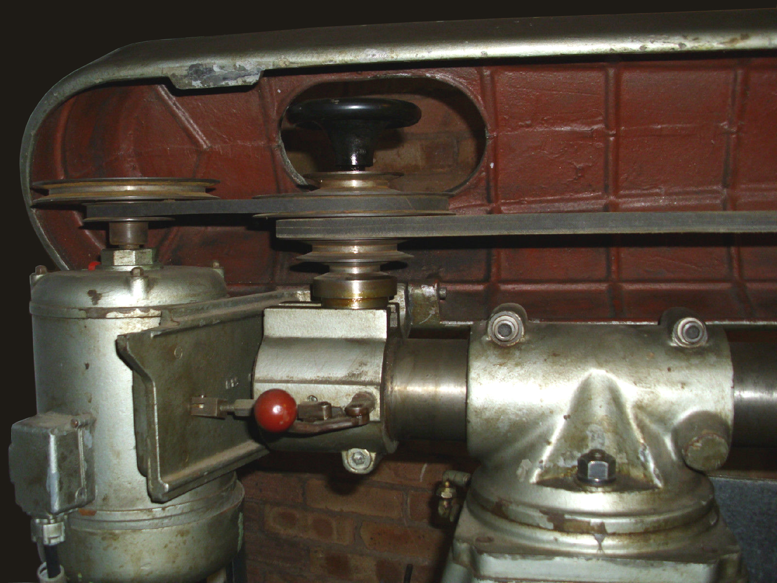
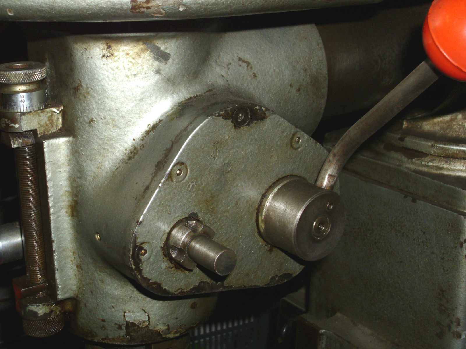
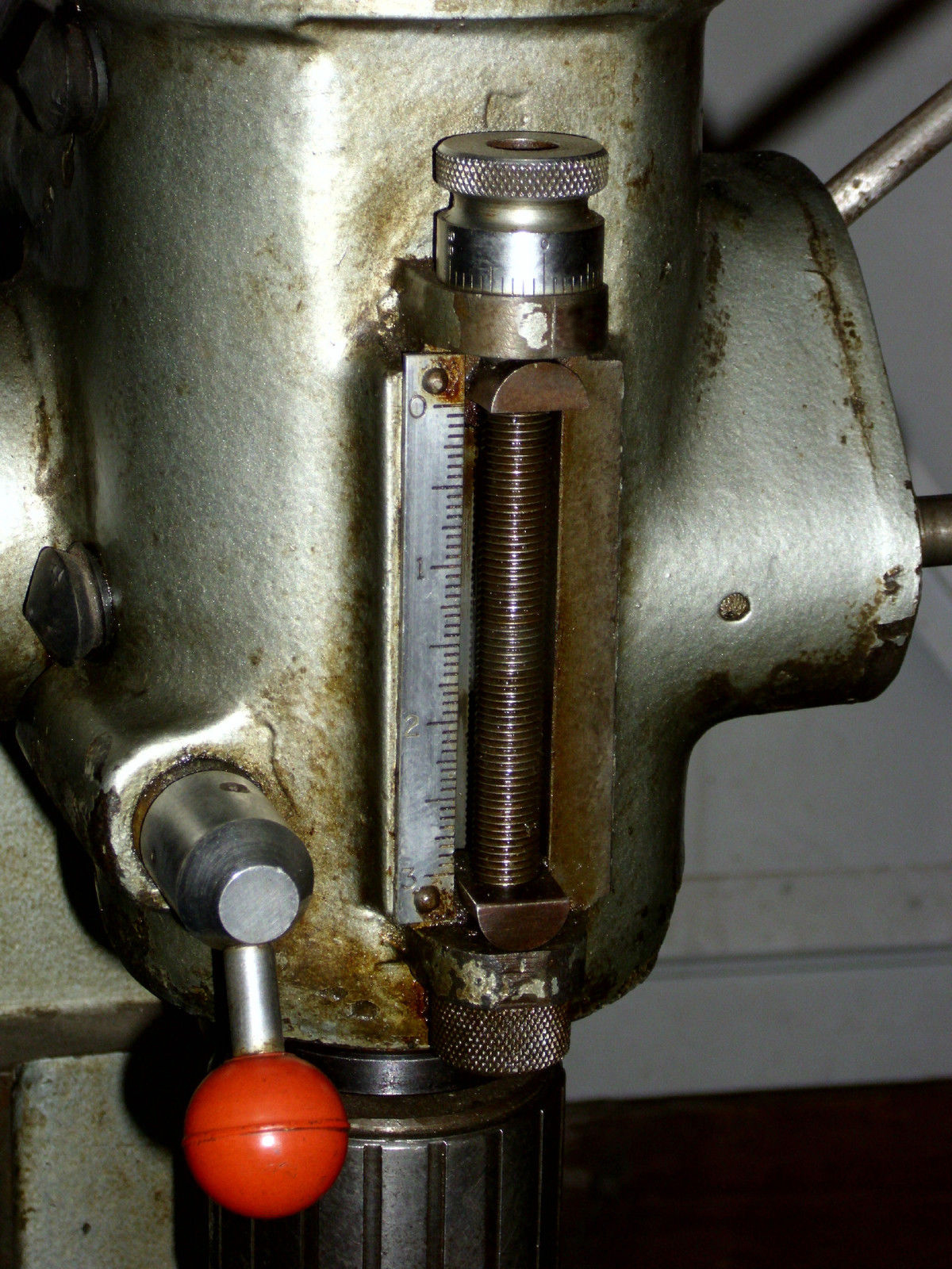
Both the "A" and "VBA" had a spindle driven by a simple, reliable two-stage V-belt arrangement, with an adjustable intermediate 5-step pulley carried on a T-slotted bracket and running on two precision, grease-packed ball bearings. A large plastic knob, with finger grips, was provided to slacken the T-bolt and allow speed changes on the front pulley - the rear belt being adjusted by an over-centre toggle lever and cam working against the motor-mount plate. Hinged from the side, a rather fragile cast-aluminium cover guarded the whole of the belt run. The most common motor fitted was a 0.75 hp 3-phase unit that gave 7 speeds in two ranges arranged (through the intermediate pulley) of 200, 330 and 500 r.p.m. in Low-Range and 850, 1420, 2200, 3600 r.p.m. on High. On some models a mechanical spindle brake was fitted, operated by a lever on the front left-hand face of the head. The head swung on top of the column, slid in and out of its housing and swivelled through 90 degrees each way - this allowed the head to cover the whole table at one setting as well bringing the spindle nose to within 3.5" of the column face or moved away to give a maximum clearance of 9.75". The 4-step pulley on the head was supported in the same type of long-life bearings (at top and bottom) as the intermediate pulley and the six-spline spindle that ran through it was hardened, ground all over and usually equipped with a No. 30 International nose. The 3-inch travel quill, hard-chromed and running in Timken "Precision 3" taper roller bearings, was fitted in a honed and lapped Meehanite housing and fitted with a mechanism that gave both fine and quick-action feeds. All the V-pulleys were made from very close-grained cast iron, machined all over and, to ensure smooth running, balanced. The quill movement was measured by a combination of a 3-inch vertical ruler, an adjustable micrometer dial and a very useful screw-adjusted 'pre-set' depth stop.
For the home or smaller professional workshop the Beaver "A" was one of the few machines that combined quality, size and functionality in just the right proportions and, because the electric motor was mounted directly onto the back of the ram, changing it for a single-phase unit is a very simple operation. Unfortunately, the flange-mounted table power-feed motor was fitted to the back of the knee and, being awkward to get at, is not such an easy prospect for modification. Today, of course, an inverter drive solves all these hitherto expense and time-consuming problems
In 1959 the "A" was listed at £300, less electrical equipment, and weighed approximately 9.5 cwt (1064 lbs) whilst the "VBA", with its more massive construction, was around 17 cwt.
Balding also built a 4.5" x 20" backgeared, screwcutting lathe of conventional design but robust construction - details of which can be found here..
|
|


