 |
 |
 |
 |
 |
 |
 |
 |
 |
 |
 |
 |
 |
 |
 |
 |
 |
 |
 |
 |
 |
 |
 |
 |
 |
 |
 |
 |
 |
 |
 |
 |
 |
 |
 |
 |
|
|
|
|
|
|
|
|
|
|
|
|
|
|
|
|
|
|
|
|
|
|
|
|
|
|
|
|
|
|
|
|
|
|
|
|
|
|
|
|
|
|
|
|
|
|
|
 |
|
|
|
|
|
|
|
|
|
BCA Jig Borer: the head in angled position. Some specification sheets gave the maximum inclination as 40°, others as 45°.Note the screw-adjustable depth stop on the left-hand side of the head.
|
|
|
|
|
|
|
|
|
|
 |
|
|
|
|
|
|
|
|
|
|
|
 |
|
|
|
|
|
|
Maker's engraving on the Sigma-Jones version of the jig borer
|
|
|
|
|
|
|
|
 |
|
|
|
|
|
|
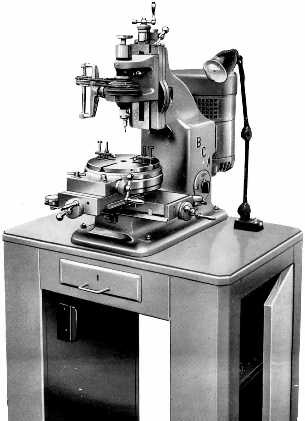
BCA Mk. 3 as made from the late 1940s with a 4-slot table - the greatly-increased mass
of the main column is clearly evident
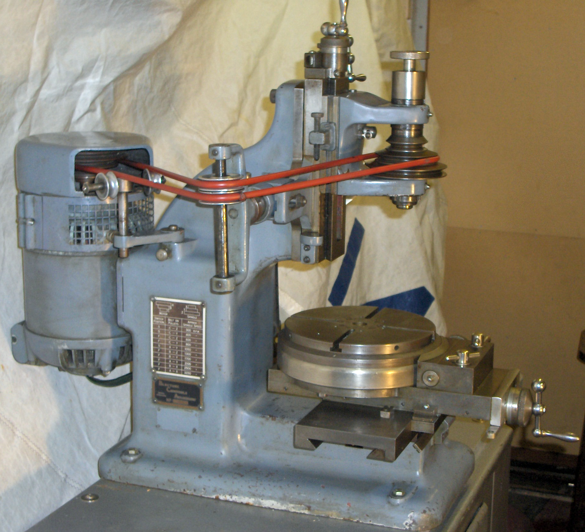
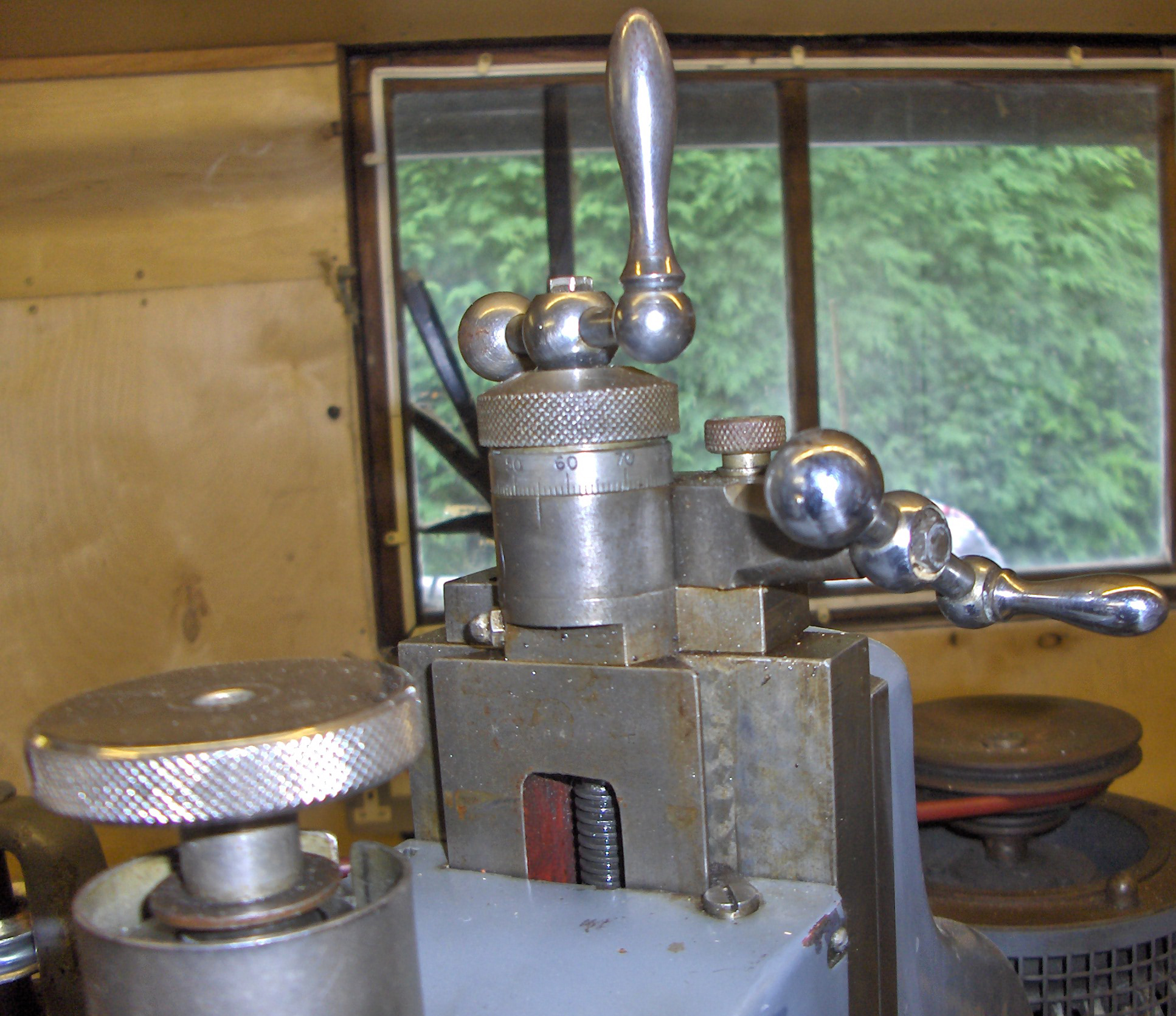
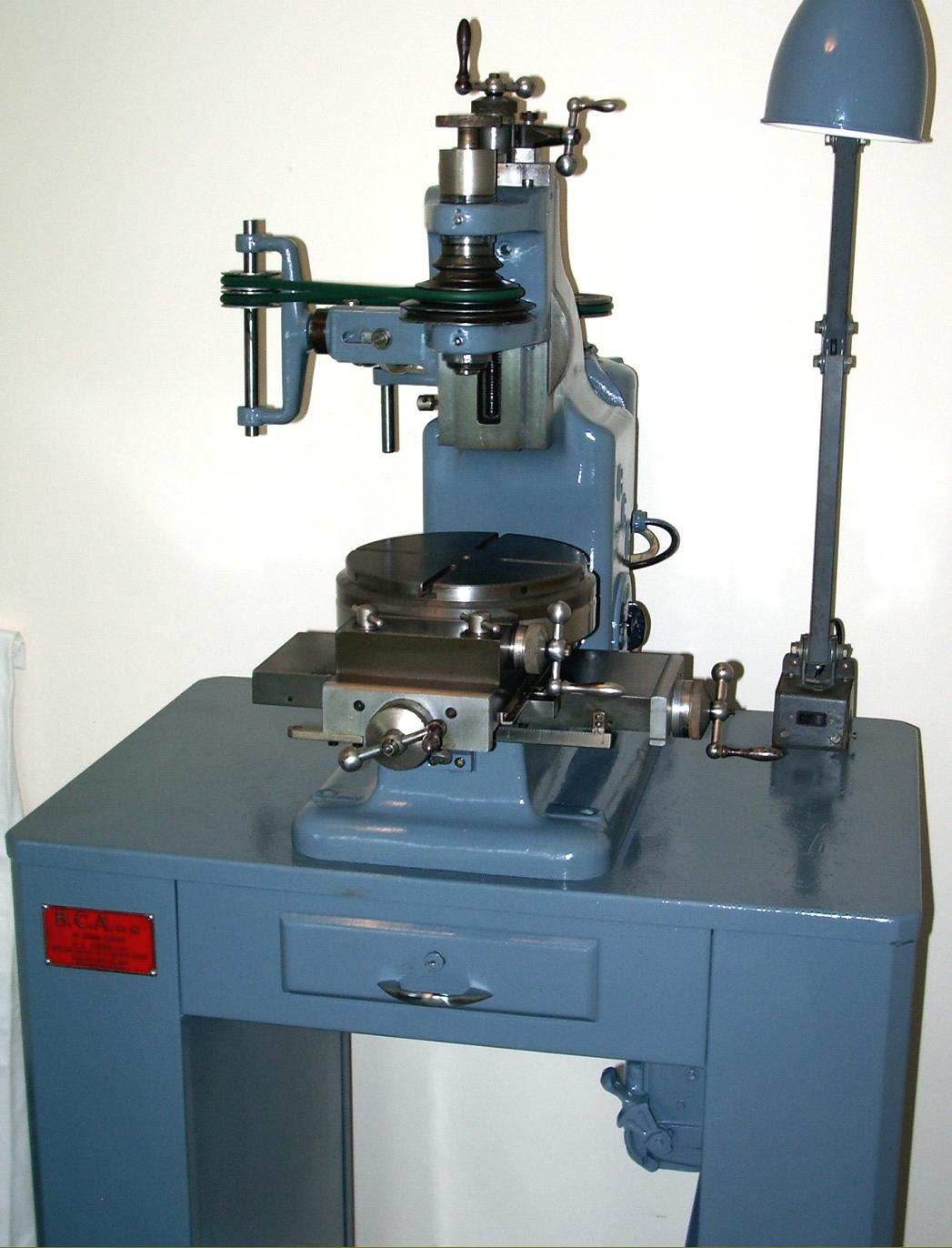
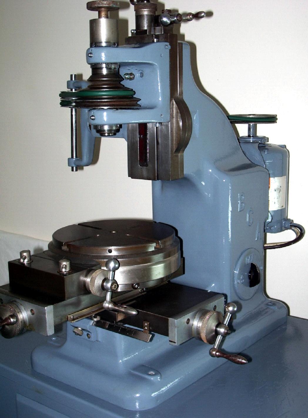
Of significantly more massive construction, with a much deeper and wider main column, this version was arranged to carry the head higher and give an extra 2 inches of clearance between spindle nose and table. Whilst the spindle and bearings remained unaltered the head castings were heavier, with slightly wider slides and the head could now be moved by either a direct-acting screw or (on some but not all machines) by a side-mounted handwheel that drove (at 90-degrees) through worm-and-wheel gearing to give an extra-fine feed - and with the travel increased to a little over 6 inches. Unfortunately these welcome modifications resulted in the head's maximum inclination being reduced from 40° or 45° to only 30°. Both elements of compound table were lengthened to give an extra two inches of travel on each axis and the feed screws equipped with ball thrust races and larger micrometer dials. The number of slots in the 8-inch rotaty table was increased to four and, by using a 2-speed 3-phase motor, 11 spindle speeds were available spanning 300 to 3250 rpm, a significant improvement on the limited and rather slow ranges available previously
|
|
|
|
|
|
|
|
|
|
|
|
|
|
|
|
|
 |
|
|
|
|
|
|
BCA Mk. 3 on the maker's cabinet stand
|
|
|
|
|
|
|
|
|
|
|
 |
|
|
|
|
|
|
Modified drive system of the Mk. 3 where, instead of a tensioning weight within the column, an extra pair of jockey pulleys was used, mounted on a swinging bracket pivoting on a bar socketed into the left-hand side of the column.
|
|
|
|
|
|
|
|
 |
|
|
|
|
|
|
|
|
The extra fine feed right-angle drive to head
|
|
|
|
|
|
|
|
|
|
 |
|
|
|
|
|
|
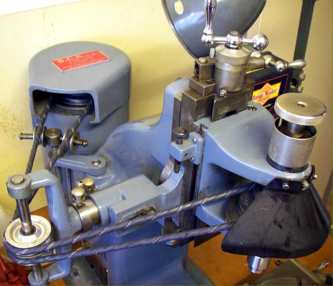
A clear view of a Mk. 3 BCA showing the second type of jockey pulley used just carried outboard of the motor pulley on a swing bracket . This system restricted the head's inclination to 30° each side of central
|
|
|
|
|
|
|
|
 |
|
|
|
|
|
|
A genuine BCA toolmakers' machine vice: 57 mm jaw width with an opening capacity of 64 mm
|
|
|
|
|
|
|
|
 |
|
|
|
|
|
|
|
BCA Mk. 3 on the maker's stand
|
|
|
|
|
|
|
|
|
|
 |
|
|
|
|
|
|
|
|
|
|
|
|
|


