 |
 |
 |
 |
 |
 |
 |
 |
 |
 |
 |
 |
 |
 |
 |
 |
 |
 |
 |
 |
 |
 |
 |
 |
 |
 |
 |
 |
 |
 |
 |
 |
 |
 |
 |
 |
 |
 |
 |
 |
 |
 |
 |
 |
 |
 |
 |
 |
 |
 |
 |
 |
 |
 |
 |
 |
 |
 |
 |
 |
 |
 |
 |
 |
 |
 |
 |
 |
 |
 |
 |
 |
 |
 |
 |
 |
 |
 |
 |
 |
 |
 |
 |
 |
 |
 |
 |
 |
 |
 |
 |
 |
 |
 |
 |
 |
 |
|
|
|
|
|
|
|
|
|
|
|
|
|
|
email: tony@lathes.co.uk
Home Machine Tool Archive Machine-tools Sale & Wanted
Machine Tool Manuals Catalogues Belts Books Accessories
Arboga, AB Skania Verktyg, Eskilstuna Tools
UM400 Miniature Combination Machine
UM400 Page 2 UM400 Katalog
Arboga Home Page Arboga Drilling Machines
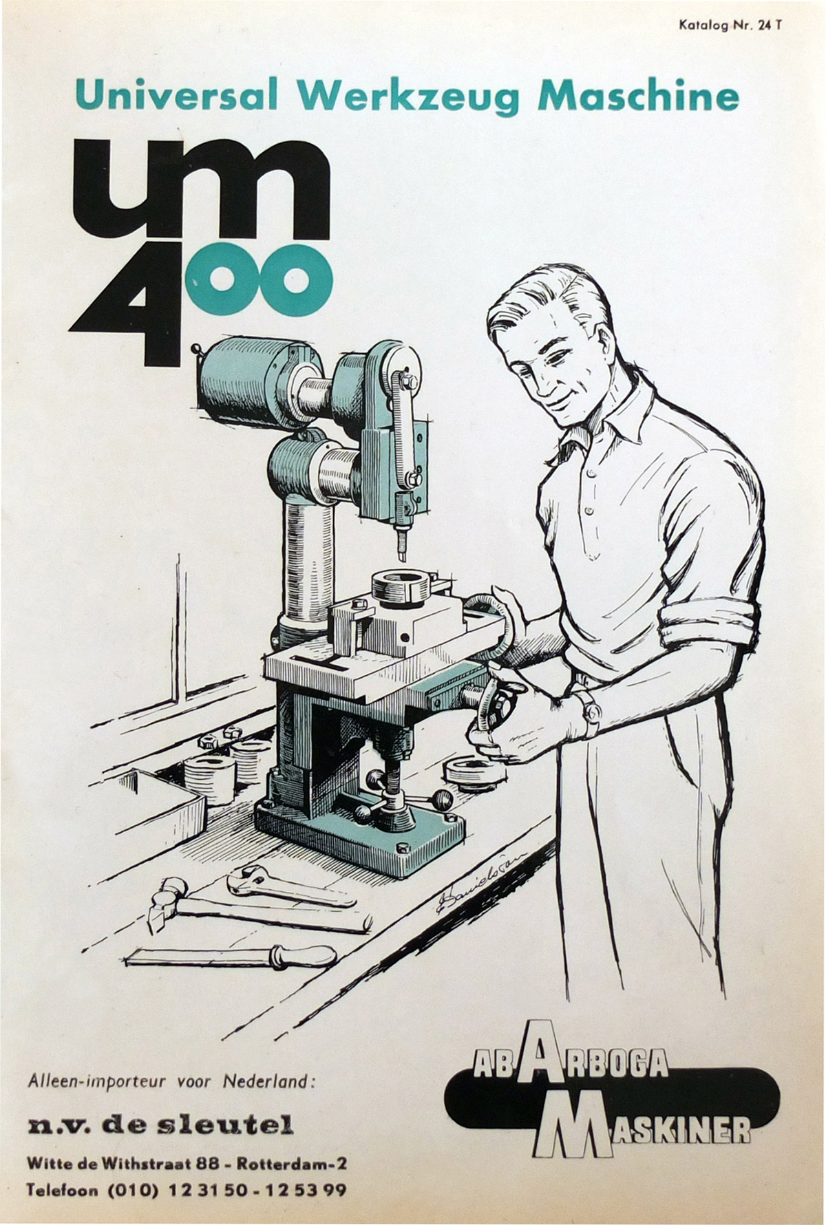
A well-illustrated catalogue is available the UM400
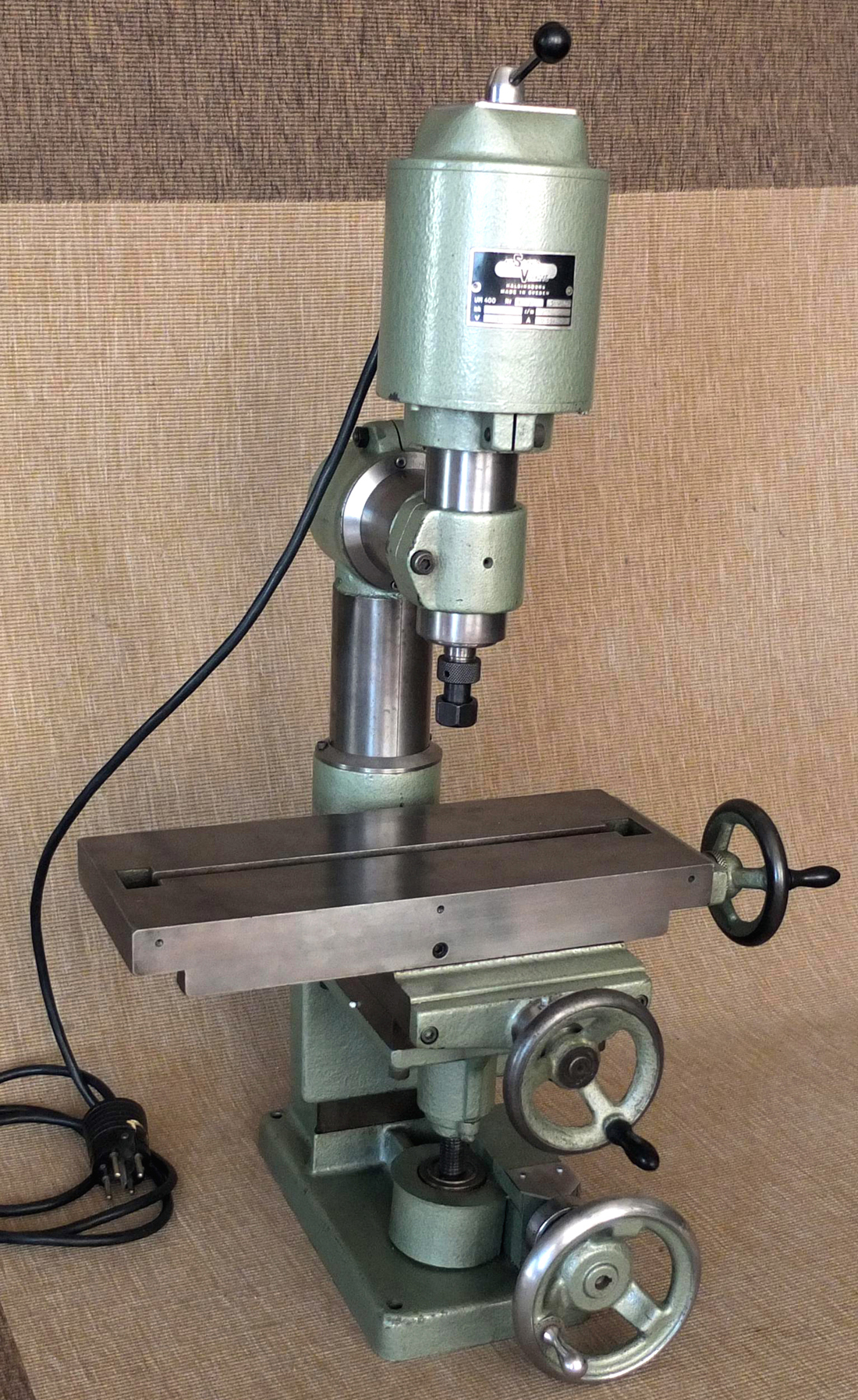
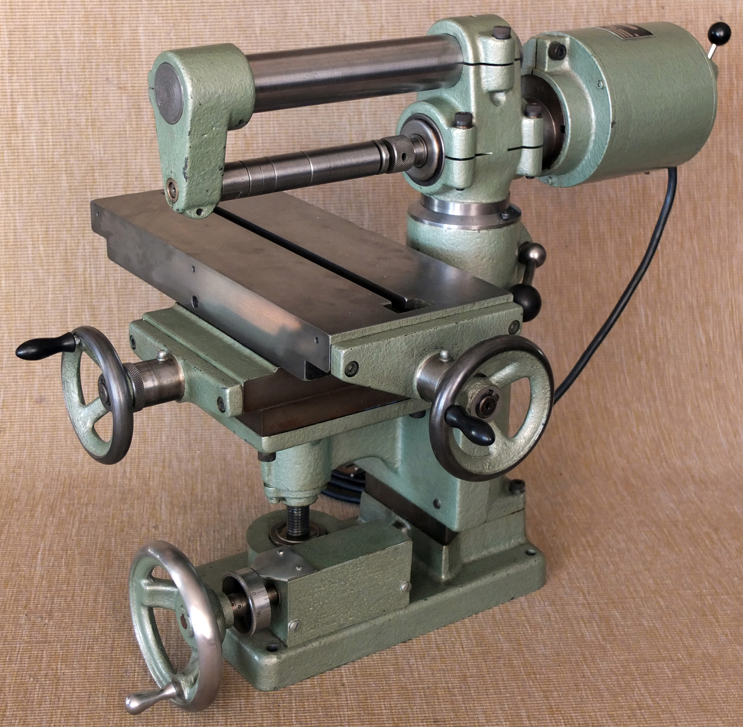
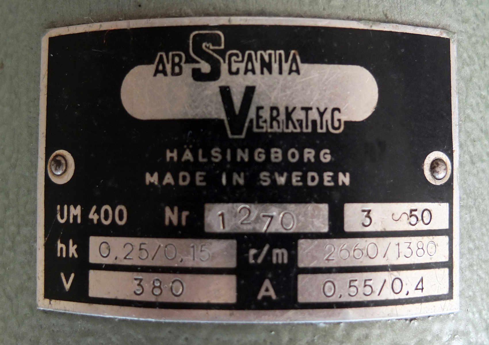
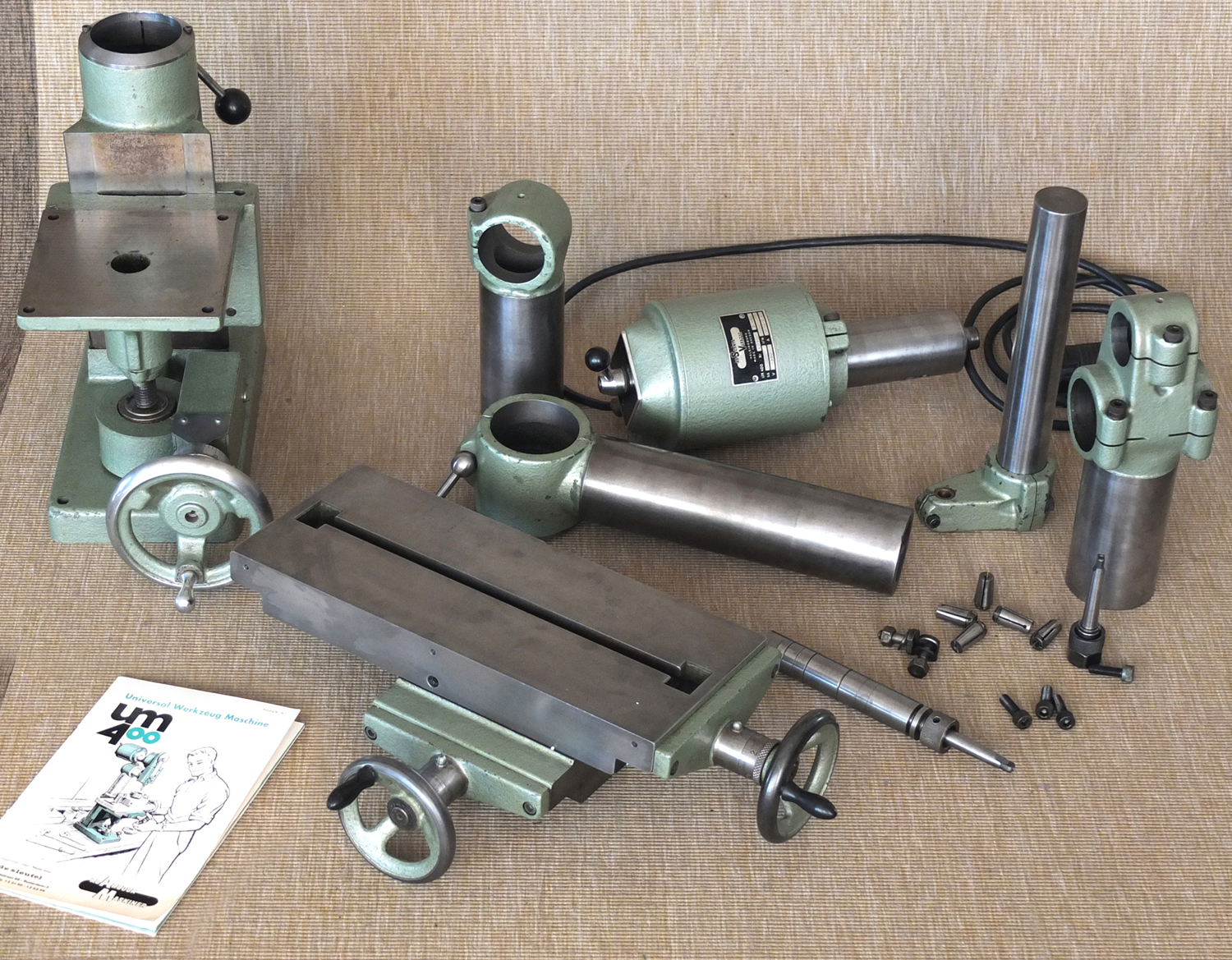
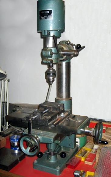
Sometimes badged as the AB Skania Verktyg and also Eskilstuna Tools (and with examples of the latter often lacking a serial number) the superbly made and highly versatile Arboga UM400 was designed as a miniature, multi-purpose machine tool able to perform vertical and horizontal milling, drilling, slotting, shaping, filing, grinding and simple lathe work. It achieved these objectives not by repositioning or adapting its major components, but rather by the addition of specific modules, each adapted to a single task. The machine's base unit was a bench-mounting 12" x 57/8" (280 mm x 150 mm) cast-iron foot together with a column, the front face of which was machined with ways to take a conventional type of milling machine "knee" - this having a simple flat surface to which was fitted a single T-slot, 14" x 57/8" (360 mm x 150 mm) compound table that had a longitudinal travel of 7 1/2" (190 mm), a cross feed of 23/4" (70 mm) and a vertical movement of 31/8" (80 mm). While most examples appear to have been fitted with knee lift by a nut fitted with a 3-spoke capstan handwheel, the AB Skania Vertyg version has been found with an alternative system, a full-circle handwheel working through worm-and-wheel gearing that gave, presumably, a finer rate of feed of 1mm rise per revolution of the handle. Micrometer-graduated collars were fitted to the feed screws and could be engraved with either inch or metric graduations.
Driven by a 50 Hz 2-speed 3-phase 0.25/0.15 h.p. 2770/1410 rpm motor, spindle speeds were: 365, 730, 1410 and 2770 r.p.m. while for the American market a 60 Hz motor gave speeds of 440, 885, 1700 and 3400 r.p.m.
In order to create the main vertical miller, a simple column (Part No. 4002) was dropped into a socket on the base (4001) and a right-angle column clamp (4003) fitted on top to hold the combined motor and spindle unit (4004). In addition to the main machine components, a range of accessories was offered that included a tilr-base rotary table, metric and Inperial Collets, a slitting saw holder, lathe toolpost, 3-jaw chuck, catchplate for between-centres work and a machine vice All the parts, accessories and their various combinations are shown below and on this page. The maker's detailed and well-illustrated catalogue (in German) cab be found here and continued here..
|
|
|
|
|
|
|
|
|
|
|
|
|
|
|
|
|
|
|
|
|
|
|
|
|
|
|
|
|
|
|
|
|
|
|
|
|
|
|
|
|
|
|
|
|
|
|
|
|
|
|
|
|
|
|
|
|
|
|
|
|
|
|
|
|
|
|
|
|
|
|
|
|
|
|
|
|
|
|
|
|
|
|
|
|
|
|
|
|
|
|
|
|
|
|
|
 |
|
 |
|
|
|
|
|
|
Base unit and table: Part 4001
|
|
|
|
|
|
|
|
 |
|
|
|
|
|
|
Horizontal Clamp Column Part 4003
|
|
|
|
|
|
|
|
 |
|
|
|
|
|
|
Motor and Spindle Part 4004
|
|
|
|
|
|
|
|
|
|
|
The vertical miller consisted of the base unit and table (4001) together with a vertical column (4002) a right-angle clamp (4003) and the spindle and motor unit (4004)
|
|
|
|
|
|
|
|
 |
|
|
 |
|
|
|
|
|
|
|
|
Tool Holder with Return Stroke Relief Part (40014) - a standard shaper-type clapper-box hinge mechanism was used but is not illustrated.
|
|
|
|
|
|
|
|
|
|
|
|
|
|
|
|
|
|
Shaper with Base (4001), Motor and Spindle (4004), complete (side-mounted) Slotting Attachment (40011) and Tool Holder with Return Stroke Relief (40014)
|
|
|
|
|
|
|
|
|
 |
|
|
|
|
|
|
 |
|
|
|
|
|
Vertical Column Part 4002
|
|
|
|
|
|
|
|
|
|
|
 |
|
|
|
|
|
|
File Holder Part 40012 for Slotting Attachment
|
|
|
|
|
|
|
|
|
|
Slotter with Base 4001, Column 4002, Motor and Spindle (4004) and the complete Slotting Attachment Head 40011
|
|
|
|
|
|
|
|
|
|
|
 |
|
|
|
|
|
|
|
|
|
|
|
Complete Slotting and Shaping Attachment Part 40011
|
|
|
|
|
|
|
|
|
|
 |
|
|
|
|
|
|
|
|
 |
|
|
|
|
|
|
|
|
Drilling Attachment Part 4005
|
|
|
|
|
|
|
|
|
|
|
|
|
 |
|
|
|
|
|
|
|
|
|
Turning Tool Holder Part 40017
|
|
|
|
|
|
|
|
|
|
|
|
|
|
|
|
 |
|
|
|
|
|
|
|
|
|
|
|
|
|
|
|
|
|
UM-400 as a drilling machine with quick-feed rack-and-pinion drive to the head.
|
|
|
|
|
|
|
|
|
|
|
|
 |
|
|
|
|
|
|
 |
|
|
|
|
|
Catchplate for between-centres turning Part 40016
|
|
|
|
|
|
|
|
|
|
|
|
|
|
|
|
|
|
|
|
|
|
The Arboga UM400 adapted as a lathe. Centre height 13/8" (35 mm) and 57/8" (150 mm) between centres.
|
|
|
|
|
|
|
|
|
|
|
|
 |
|
|
|
|
|
|
|
|
|
Turning Attachment Column with Tailstock Part 40015
|
|
|
|
|
|
|
|
|
|
 |
|
 |
|
|
|
|
|
Grinding Wheel Shatter Guard part 40010
|
|
|
|
|
|
|
|
|
|
|
|
|
|
 |
|
|
|
|
|
|
|
|
Grinding Wheel Holder Part 4009
|
|
|
|
|
|
|
|
|
|
|
|
|
 |
|
|
|
|
|
|
Motor and Spindle Part 4004
|
|
|
|
|
|
|
|
|
|
|
|
|
|
As a grinder the UM-400 required the Base (4001), Motor and Spindle (4004), Clamp (4003), Grinding Wheel Holder (4009) and a Shatter Guard (40010)
|
|
|
|
|
|
|
|
|
|
 |
|
|
|
 |
|
|
|
|
|
|
|
|
|
|
|
 |
|
|
|
|
|
|
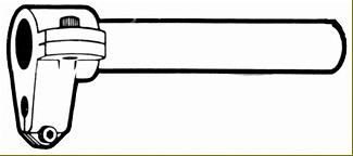
Overarm Part 4007 (the design differed)
|
|
|
|
|
|
|
|
 |
|
|
|
|
|
|
|
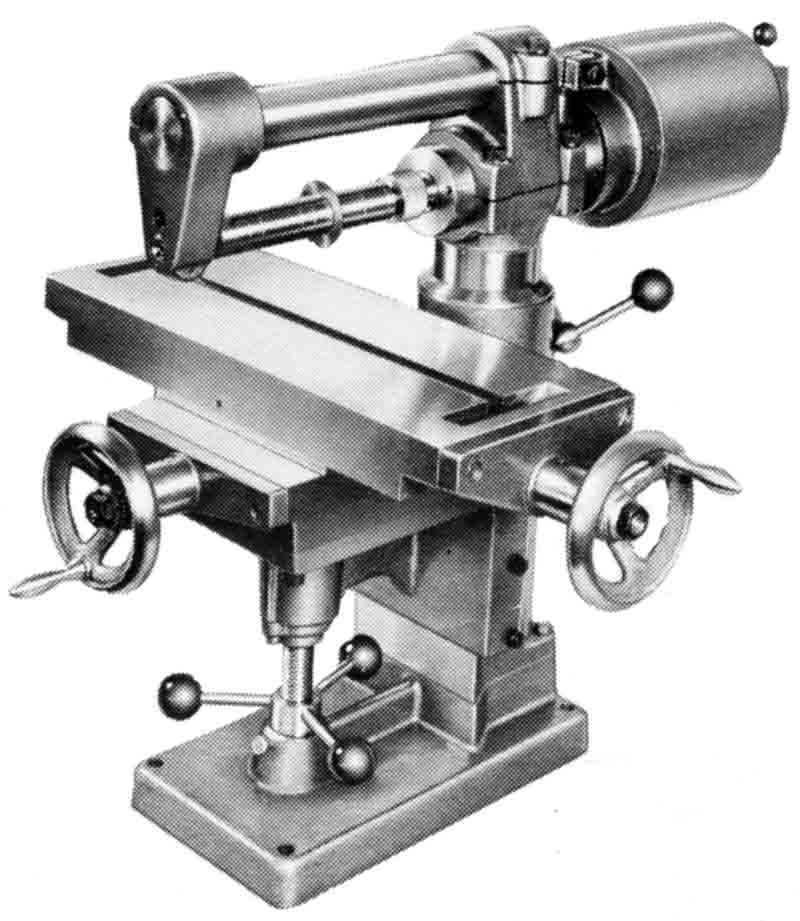
Horizontal Milling machine with Base (4001), Motor and Spindle 4004, Milling Column (4006), Overarm with bearing (4007), and Cutter Arbor (4008).
|
|
|
|
|
|
|
|
|
|
|
|
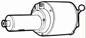
Motor and Spindle Part 4004
|
|
|
|
|
|
|
|
|
|
|
|
|
|
|
 |
|
|
|
|
|
|
|
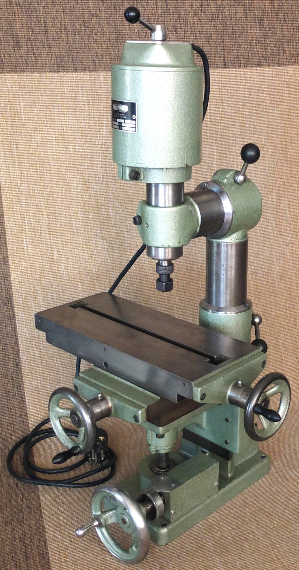
A splendid example of the UM400 badged as an "AB Scania Verktyg" and fitted with an extra-fine vertical feed by a handwheel working through worm-and-wheel gearing.
|
|
|
|
|
|
|
|
|
 |
|
|
|
|
|
|
|
|
|
 |
|
|
|
 |
|
|
|
|
 |
|
|
|
|
|
|
|
|
 |
|
|
|
|
 |
|
|
|
|
|
|
|
|
|
Arboga UM400 badged as an AB Skania
|
|
|
|
|
|
|
|
|
|
|
|
|
|
|
|
|


